Aerial cable

A high-altitude cable and cable technology, which is applied in the direction of overhead lines/cable equipment, etc., can solve the problems of high work intensity of installers, difficulty in tightening the cable body, and large force of cable use, so as to reduce work intensity, simplify and save labor The effect of tightening and reducing friction

Active Publication Date: 2021-08-10
GUANGXI WANG LIAN WIRE & CABLE CO LTD
View PDF9 Cites 1 Cited by
  • Summary
  • Abstract
  • Description
  • Claims
  • Application Information

AI Technical Summary

Problems solved by technology

[0003] The object of the present invention is to provide a high-altitude cable to solve the existing problem: when the existing high-altitude cable is erected, due to the heavy gravity of the cable itself, the installer uses a large force when pulling the cable, causing the installer to The working intensity of the cable is relatively high, and it is difficult to tighten the cable body when the cable is laid

Method used


Image

  • Aerial cable
  • Aerial cable
  • Aerial cable

Examples


Embodiment 1

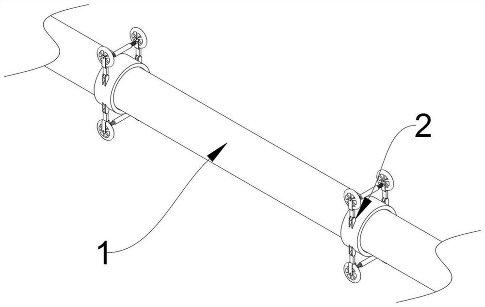
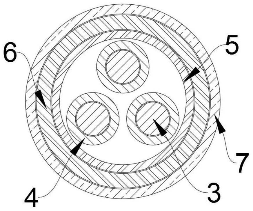
[0032] see Figure 1-4 As shown, the present invention is a high-altitude cable, including a cable body 1. The cable body 1 includes a plurality of cable copper cores 3, and the outer sides of the cable copper cores 3 are provided with copper core protective sleeves 4 for protecting the cable copper cores 3. To protect and separate the cable copper core 3 from the adjacent cable copper core 3, an insulating protective layer 5 is provided on the outside of the plurality of copper core protective sleeves 4 to isolate and insulate the electric energy released by the cable copper core 3 The outer side of the protective layer 5 is provided with a metal braided protective layer 6, which is used to protect the copper core protective sheath 4 to prevent the copper core protective sheath 4 from being damaged by external force, and the outer side of the metal braided protective layer 6 is provided with a cable protective layer 7 for Prevent the metal braided protective layer 6 from bein...

Embodiment 2

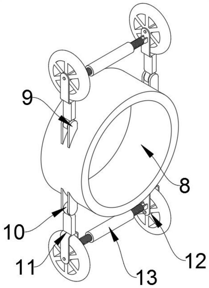
[0038] see Figure 5-8 As shown, another auxiliary mechanism 2 is disclosed on the basis of Embodiment 1. The auxiliary mechanism 2 includes a second cable fixing ring 29, and the upper end of the second cable fixing ring 29 is fixedly connected with a C-shaped fixing bracket 18, and the C-shaped The lower end of one side of the fixed frame 18 is fixedly connected with a shaft plate limit ring 19, and the inside of the shaft plate limit ring 19 is slidably connected with a lifting shaft plate 28, and the upper end of the lifting shaft plate 28 is fixedly connected with a guide shaft plate 24, and the guide shaft plate Both ends of 24 are provided with a first cable guiding slope;

[0039] The lower end of the shaft plate limit ring 19 is fixedly connected with a spring limit ring 20, and the inside of the spring limit ring 20 is provided with a return force spring 22, and the upper end of the return force spring 22 is fixedly connected with the lifting shaft plate 28;

[0040] ...


PUM


Abstract

The invention discloses an aerial cable, and relates to the technical field of aerial cable laying. The aerial cable comprises a cable body, wherein an auxiliary mechanism is arranged on the outer side of the cable body and used for assisting installation of the cable body. The angle of a movable pulley is adjusted by rotating a threaded sleeve, so that the movable pulley can move in bridges of different sizes, the contact area of the cable body and the bridges is reduced, and the friction force between the cable body and the bridges can be effectively reduced through rotation of the movable pulley, so that the cable body can be pulled in a labor-saving mode, and the cable body can be simply tensioned when the cable is laid. In the erecting process, an auxiliary cable bears the gravity of the cable body through a C-shaped fixing frame, the force used by the installation personnel when the cable is pulled is effectively reduced, the work intensity of the installation personnel is greatly reduced, and the cable body can be tensioned simply in a labor-saving manner when the cable is laid.

Description

technical field [0001] The invention belongs to the technical field of high-altitude cable laying, in particular to a high-altitude cable. Background technique [0002] A cable is an electrical energy or signal transmission device, usually composed of several wires or groups of wires. Due to the use of cables, the length of the cable is reduced and the construction cost is reduced. The cable is often erected in a high-altitude environment, but the existing high-altitude When the cable is erected, due to the heavy gravity of the cable itself, the installer uses a lot of force when pulling the cable, resulting in a greater work intensity for the installer, and it is more difficult to tighten the cable body when the cable is laid. Contents of the invention [0003] The object of the present invention is to provide a high-altitude cable to solve the existing problem: when the existing high-altitude cable is erected, due to the heavy gravity of the cable itself, the installer u...

Claims


Application Information

Patent Timeline
Patent Type & Authority Applications(China)
IPC IPC(8): H02G1/04
CPCH02G1/04
Inventor 柳玉军
Owner GUANGXI WANG LIAN WIRE & CABLE CO LTD
Why Eureka
Try Eureka