Dust sticking device for polaroid production

A technology of polarizers and sticky rollers, applied in cleaning methods and utensils, chemical instruments and methods, etc., can solve the problems of large overall size, difficulty in installation, easy jamming, and bulky volume, etc., and achieve efficient and convenient cleaning

Inactive Publication Date: 2021-08-13
SHENZHEN SAPO PHOTOELECTRIC
5 Cites 0 Cited by

AI-Extracted Technical Summary

Problems solved by technology

[0002] With the development of related industries such as the production of large-size partial-off film, the requirements for membrane cleaning are getting higher and higher. The membrane cleaning equipment on the market is expensive and bulky. At the same time, online cleaning cannot be achieved. Membrane cleaning equipment needs to be based on The space location of the master device is changed depending on the location, and there are mainly the following de...

Method used

In the present embodiment, adopt described linear slide rail 5, can make whole described bearing base 6, described bearing seat 7 move more smoothly, do not freeze, can not rub off powder, avoid polluting clean room And the polarizer film material; and the load capacity becomes larger, and a larger and heavier sticky dust roller 1 can be installed.
The beneficial effect of sticky dust device for polarizer production of the present invention is: the present invention, through above-mentioned technical scheme, comprises the cylindrical sticky dust roller that is used to clean polarizer film, is installed in described sticky dust roller two ends, for The drive mechanism that drives the sticky dust roller to move up and down is used to install the "7" type mounting seat of the drive mechanism, wherein the drive mechanism is slidingly connected to the mount seat, and the drive mechanism is connected to the sticky dust roller. The rollers can be detachably connected, which is convenient for later disassembly, maintenance and replacem...

Abstract

The invention discloses a dust sticking device for polaroid production, which comprises a cylindrical dust sticking roller used for cleaning a polaroid film, driving mechanisms mounted at two ends of the dust sticking roller and used for driving the dust sticking roller to move up and down, and a 7-shaped mounting seat used for mounting the driving mechanisms, wherein the driving mechanisms are connected with the mounting seat in a sliding manner, and the driving mechanisms are detachably connected with the dust sticking roller. Compared with the prior art, the dust sticking device has the advantages that the dust sticking roller is convenient to disassemble, maintain and replace in the later period, and the dust sticking device is efficient and convenient to clean.

Application Domain

Cleaning processes and apparatus

Technology Topic

PhysicsEngineering +1

Image

  • Dust sticking device for polaroid production
  • Dust sticking device for polaroid production

Examples

  • Experimental program(1)

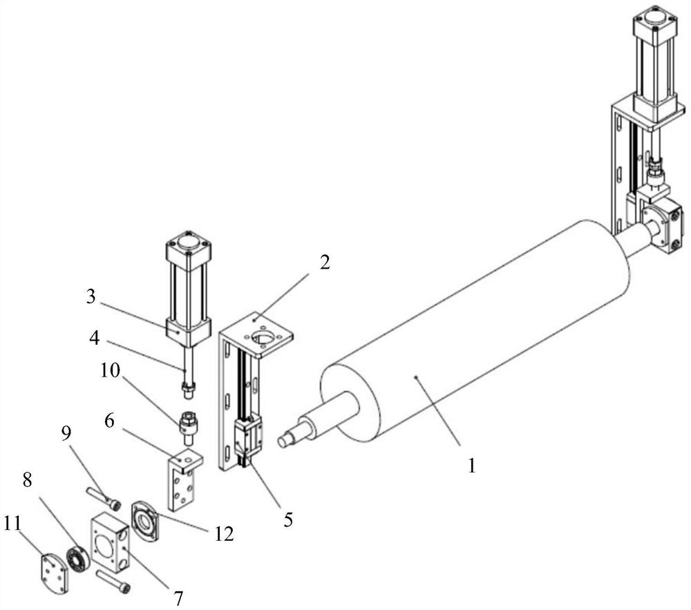
Example Embodiment

[0020] Next, the technical solutions in the embodiments of the present invention will be described in contemplation in the embodiments of the present invention, and clearly, as described herein is merely, not all of the embodiments of the present invention. Based on the embodiments of the present invention, those of ordinary skill in the art will belong to the scope of the present invention without all other embodiments obtained without creative labor.
[0021] It should be noted that if there is a directional indication (such as above, lower, left, right, post, post, ...), the directional indication is only used to interpret a particular attitude (such as the figures) Sign) The relative positional relationship between the components, movement conditions, etc., if the specific posture changes, the directional indication is also changed accordingly.
[0022] Further, in the embodiment of the present invention relates to a description of "first", "second", the description of the "first", "second", etc., is only used to describe the purpose, and cannot be understood as an indication or implied Its relative importance or implicitly indicated the number of technical features indicated. Thus, features with "first", "second" may be indicated or implicitly including at least one of this feature. In addition, the meaning of "and / or" in full text, including three parallel schemes, as examples "A and / or B", including A schemes, or B regions, or A and B simultaneously satisfied. In addition, the technical solution between the various embodiments can be combined with each other, but it must be based on those of ordinary skill in the art. When the combination of technical solutions appear or unable to implement, the combination of this technical solution does not exist. It is not within the scope of the claims of the present invention.
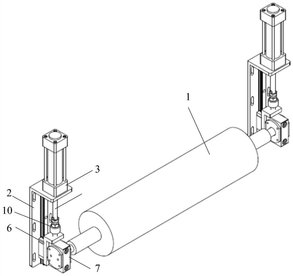
[0023] Please refer to figure 1 and figure 2 According to the present invention, a polarizer production is proposed. The preferred embodiment of the polarizer production of the present invention includes a cylindrical dust roller 1 for cleaning the polarizing film, mounted to the viscous dust roller 1. At the end, the drive mechanism for driving the viscous dust roller 1 up and down, for mounting the mount 2 of the drive mechanism, wherein the drive mechanism slides to the mount 2, the drive mechanism and The viscous roller 1 is detachable.
[0024] Specifically, the drive mechanism includes a cylinder 3, a straight rail 5, a bearing base 6, a bearing base 7, and a bearing 8, wherein the linear slide 5 is mounted on the mount 2, the bearing base 6 mount On the linear slide 5, the bearing base 6 is slidably connected to the mount 2 by the linear slide rail, and the cylinder rod 4 of the cylinder 3 is connected to the bearing base 6, the bearing housing 7 Removable is mounted on the bearing base 6, the bearing 8 is mounted in the bearing seat 7, and both ends of the viscous dust roller 1 are respectively attached to the corresponding bearing 8.
[0025] When the implementation is implemented, the mount 2 can be set to "7", and the cylinder 3 is mounted on top of the mount 2, and the linear slide 5 is vertically mounted to the mount 2. On the top of the mount 2, the through hole for passing through the cylinder rod 4 of the cylinder 3 is opened.
[0026] In this embodiment, the linear slide 5 can be used, and the entire bearing base 6 can be made smoother, the bearing housing 7 is more smooth, not card, does not rub the powder, avoid polluting dust-free chamber and polarizing plates. The film material; and the load capacity becomes large, and the apparatus can be more dimensionally and more heavy.
[0027] Further, in the present embodiment, the bearing housing 7 is detachably coupled to the bearing base 6, and when the screw 9 can be mounted on the bearing base 6, when the bearing base 6 is detachably connected. When repairing or replacing the viscous roller 1, simply removing the bearing housing 7 can complete the dilatation roller 1 replacement, relatively thin, easy to disassemble, easy to disassemble, easy to achieve different specifications The installation and use of dust roller 1 is not affected by the size and length dimension of the viscous dust roller 1, and is versatile.
[0028] The drive mechanism further includes a floating joint 10 that is coupled to the bearing base 6 through the floating joint 10.
[0029] The present embodiment is known from the floating joint 10, commonly known as the universal joint, and the cylinder rod 4 can be avoided when the housing 7 is hosted and the bearing housing is locked in the same line motion.
[0030] The outer side cover of the bearing housing 7 is provided with a first cover plate 11, and the inner cover is provided with a second cover plate 12. The first cover plate 11 and the second cover plate 12 can avoid dust into the bearing seat 7, thereby increasing life.
[0031] The assembly relationship and working principle of the polarizer production of the polarizer production of the present invention will be described below.
[0032] The assembly relationship of the main structure of the polarizer production of the polarizer production of the present invention is: the cylinder 3 is assembled with the mounting seat 2, the bearing base 6 assembled with the linear slide 5, the cylinder rod 4 connection The floating joint 10 is connected to the bearing base 6.
[0033] The assembly of the paste roller 1 and the bearing housing 7 in the polarized dust collector of the present invention is: the bearing 8 is mounted inside the bearing 7, and the first cover plate 11 is mounted on both sides. And the second cover plate 12, the viscous roller 1 is mounted in the bearing housing 7, and then mounted on the entire bearing seat 7 to the bearing base 6, locks with a screw 9.
[0034] At the time of cleaning, the cylinder rod 4 extends, pushes the bearing base 6 by the floating joint 10 to slide back and forth in the slide, which in turn urges the viscous roller 1 to lower it, contact the polarizer. The film is cleaned.
[0035] When not in use, the cylinder rod 4 is retracted, and the bearing base 6 and the bearing seat 7 are slidably slidably in the linear slide 5, and the dust roller is realized. 1 Leave the polarizer membrane surface.
[0036] The advantageous effect of the polarizer production of the polarizer of the present invention is that the present invention includes a cylindrical dust roll for cleaning the polarizing film, mounted on both ends of the viscous dust roller for driving. The mounted drive mechanism for mounting the mounted drive mechanism is mounted to mount the drive mechanism, wherein the drive mechanism is slidably connected to the mounting, the drive mechanism and the dust roller detachable. Connection, facilitates the replacement of the viscosity roller later, and clean and efficient.
[0037] It is intended to be the preferred embodiment of the present invention, and is not limited to the patent scope of the present invention, and an equivalent structure conversion is made by the present invention and the present invention, or directly / indirectly. Other related technical fields are included within the scope of the present invention.

PUM

no PUM

Description & Claims & Application Information

We can also present the details of the Description, Claims and Application information to help users get a comprehensive understanding of the technical details of the patent, such as background art, summary of invention, brief description of drawings, description of embodiments, and other original content. On the other hand, users can also determine the specific scope of protection of the technology through the list of claims; as well as understand the changes in the life cycle of the technology with the presentation of the patent timeline. Login to view more.
Why Eureka
Try Eureka