

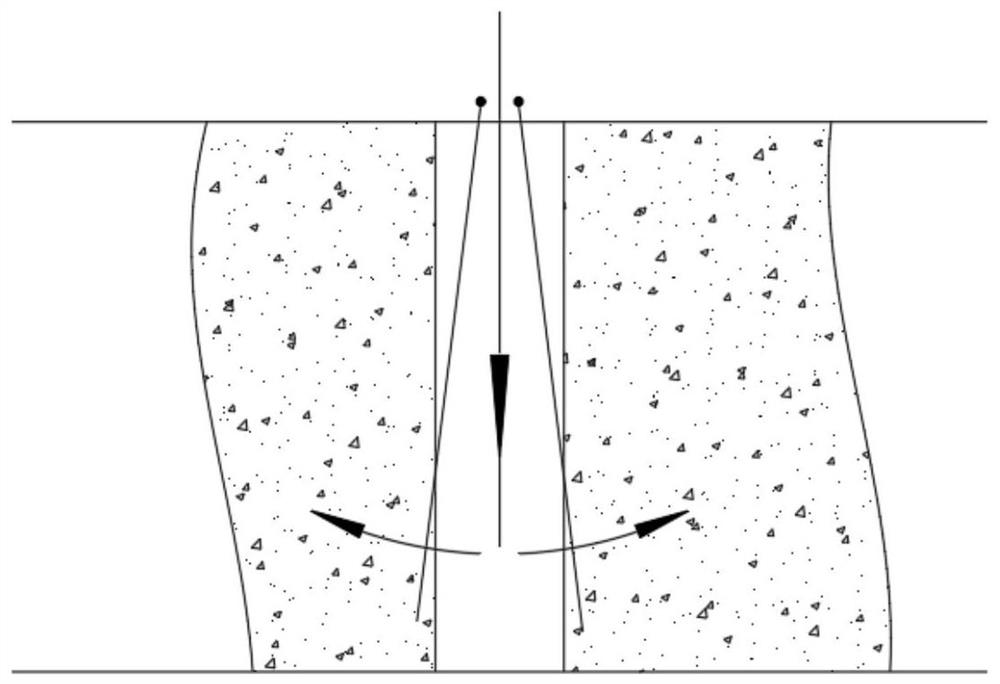
Splitter for breaking stone or concrete
A concrete and splitter technology, applied in the direction of stone processing tools, stone processing equipment, work accessories, etc., can solve the problem of increasing the load pressure and stroke pressure of the hydraulic transmission mechanism, breaking rock or concrete structures, low separation efficiency, stability and reliability Poor performance and other problems, to achieve the effect of reducing load pressure and stroke pressure, reducing expansion pressure and improving efficiency
- Summary
- Abstract
- Description
- Claims
- Application Information
AI Technical Summary
Problems solved by technology
Method used
Image

Examples
Embodiment Construction
[0021] The following will clearly and completely describe the technical solutions in the embodiments of the present invention with reference to the accompanying drawings in the embodiments of the present invention. Obviously, the described embodiments are only some, not all, embodiments of the present invention. Based on the embodiments of the present invention, all other embodiments obtained by persons of ordinary skill in the art without making creative efforts belong to the protection scope of the present invention.
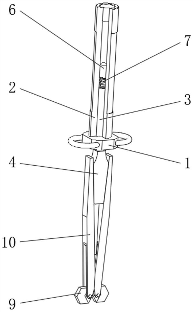
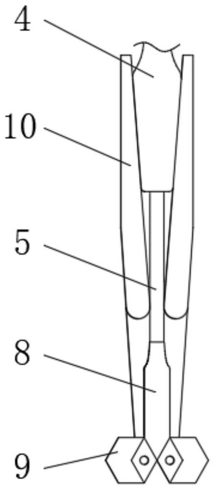
[0022] see Figure 2-3 , a splitting machine for crushing stonework concrete, including a mounting bracket 1, a pressure sleeve 2 is fixedly installed on the top of the mounting bracket 1, and a transmission connecting rod I3 is movably sleeved on the bottom of the inner wall of the pressure sleeve 2, and the transmission connecting rod The bottom end of I3 runs through and extends to the bottom of the mounting bracket 1 and is fixedly installed with a wedge b...
PUM
 Abstract
Description
Claims
Application Information