A fingerprint Ethernet electrical port physical lock device
A technology of Ethernet and physical locks, applied in the direction of coupling devices, two-part connecting devices, parts of connecting devices, etc., can solve problems such as being broken by pressure, easy to be deformed by pressure, inconvenient maintenance or debugging, etc., to avoid damage and use convenient effect
- Summary
- Abstract
- Description
- Claims
- Application Information
AI Technical Summary
Problems solved by technology
Method used
Image
Examples
Embodiment 1
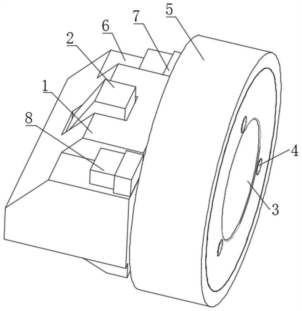
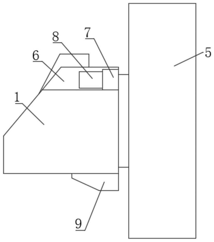
[0050] Implementation Example 1: Refer to Figure 1-8 , a physical lock device for fingerprint Ethernet electrical port provided by the present invention: comprising:
[0051] Lock body 1, the shape of lock body 1 matches the RJ45 network port; fingerprint lock module 3;
[0052] Also includes:
[0053] The lock tongue structure 2, the side of the lock body 1 is provided with an oblique opening, and the lock tongue structure 2 is arranged at the oblique opening of the lock body 1;
[0054] The transmission structure 5, the transmission structure 5 is arranged on the inner side and the right side of the lock body 1, and the dead bolt structure 2 can be withdrawn by rotating the transmission structure 5;
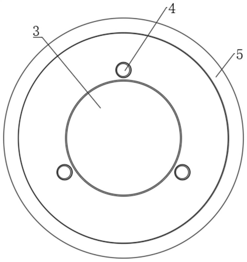
[0055] The fingerprint lock module 3 is installed on the right side of the transmission structure 5, and the fingerprint lock module 3 can prevent the transmission structure 5 from rotating when it is not unlocked;
[0056] The chute opening 6 is set on the top of the lock ...
Embodiment 2
[0060] Implementation Example 2: Reference Figure 2 to Figure 8 , the deadbolt structure 2 includes:
[0061] The deadbolt installation opening 201, the deadbolt installation opening 201 is opened on the top of the lock body 1, and the side of the deadbolt installation opening 201 is provided with a limit notch 205;
[0062] The deadbolt body 203, the deadbolt body 203 is located inside the deadbolt installation opening 201, the top of the deadbolt body 203 is provided with an oblique opening, and the bottom of the deadbolt body 203 and the inner bottom of the deadbolt installation opening 201 are provided with a spring 202 The bottom surface of the bolt body 203 is provided with a first chute 206, the inside of the first chute 206 is slidably connected with a sliding limit block 207, and one end of the sliding limit block 207 extends into the inside of the limit notch 205, the sliding limit An elastic rod 208 is disposed between the other end of the position block 207 and t...
PUM
 Abstract
Description
Claims
Application Information
 - R&D
- Intellectual Property
- Life Sciences
- Materials
- Tech Scout
- Unparalleled Data Quality
- Higher Quality Content
- 60% Fewer Hallucinations
Browse by: Latest US Patents, China's latest patents, Technical Efficacy Thesaurus, Application Domain, Technology Topic, Popular Technical Reports.
© 2025 PatSnap. All rights reserved.Legal|Privacy policy|Modern Slavery Act Transparency Statement|Sitemap|About US| Contact US: help@patsnap.com


