Optical system, camera module and electronic equipment

A technology of optical system and optical axis, applied in the direction of optics, optical components, instruments, etc.

Active Publication Date: 2021-08-13
TIANJIN OFILM OPTO ELECTRONICS CO LTD
View PDF6 Cites 2 Cited by
  • Summary
  • Abstract
  • Description
  • Claims
  • Application Information

AI Technical Summary

Problems solved by technology

[0004] Based on this, it is necessary to provide an optical system, a camera module and an electronic devi

Method used


Image

  • Optical system, camera module and electronic equipment
  • Optical system, camera module and electronic equipment
  • Optical system, camera module and electronic equipment

Examples


no. 1 example

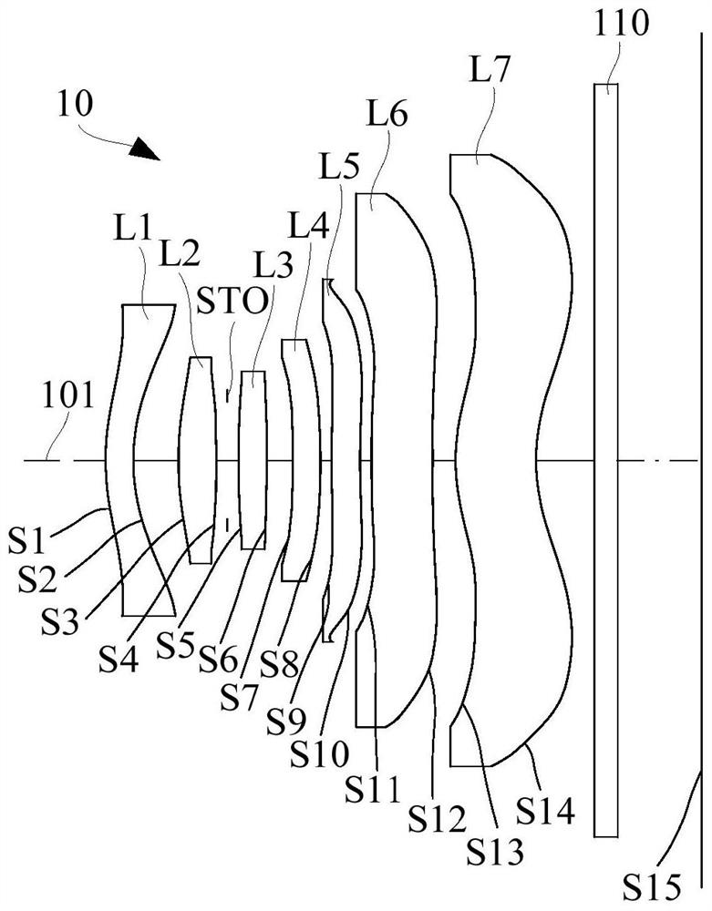
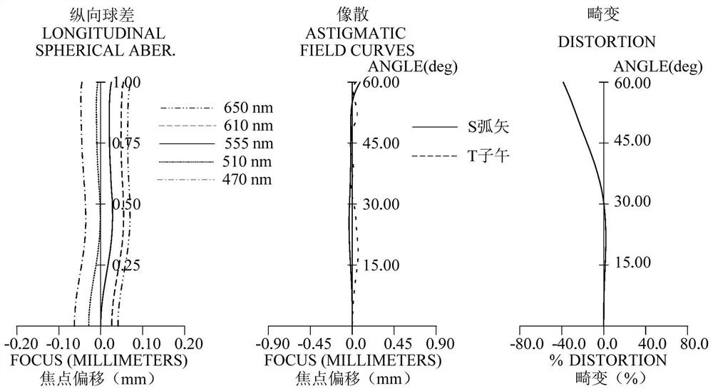
[0079] refer to figure 1 , in the first embodiment, the optical system 10 includes a first lens L1 with negative refractive power, a second lens L2 with positive refractive power, an aperture stop STO, and a lens with positive refractive power from the object side to the image side along the optical axis 101. The third lens L3 with a refractive power, the fourth lens L4 with a positive refractive power, the fifth lens L5 with a negative refractive power, the sixth lens L6 with a positive refractive power, and the seventh lens L7 with a negative refractive power. Each lens surface type of optical system 10 is as follows:

[0080] The object side S1 of the first lens L1 is convex at the near optical axis, and the image side S2 is concave at the near optical axis; the object side S1 is convex near the maximum effective aperture, and the image side S2 is concave near the maximum effective aperture .

[0081] The object side S3 of the second lens L2 is convex at the near optical ...

no. 2 example

[0108] refer to image 3 , in the second embodiment, the optical system 10 includes a first lens L1 with positive refractive power, a second lens L2 with positive refractive power, an aperture stop STO, and a lens with negative refractive power along the optical axis 101 from the object side to the image side. The third lens L3 with a refractive power, the fourth lens L4 with a positive refractive power, the fifth lens L5 with a negative refractive power, the sixth lens L6 with a positive refractive power, and the seventh lens L7 with a negative refractive power. Each lens surface type of optical system 10 is as follows:

[0109] The object side S1 of the first lens L1 is convex at the near optical axis, and the image side S2 is concave at the near optical axis; the object side S1 is convex near the maximum effective aperture, and the image side S2 is concave near the maximum effective aperture .

[0110] The object side S3 of the second lens L2 is convex at the near optical...

no. 3 example

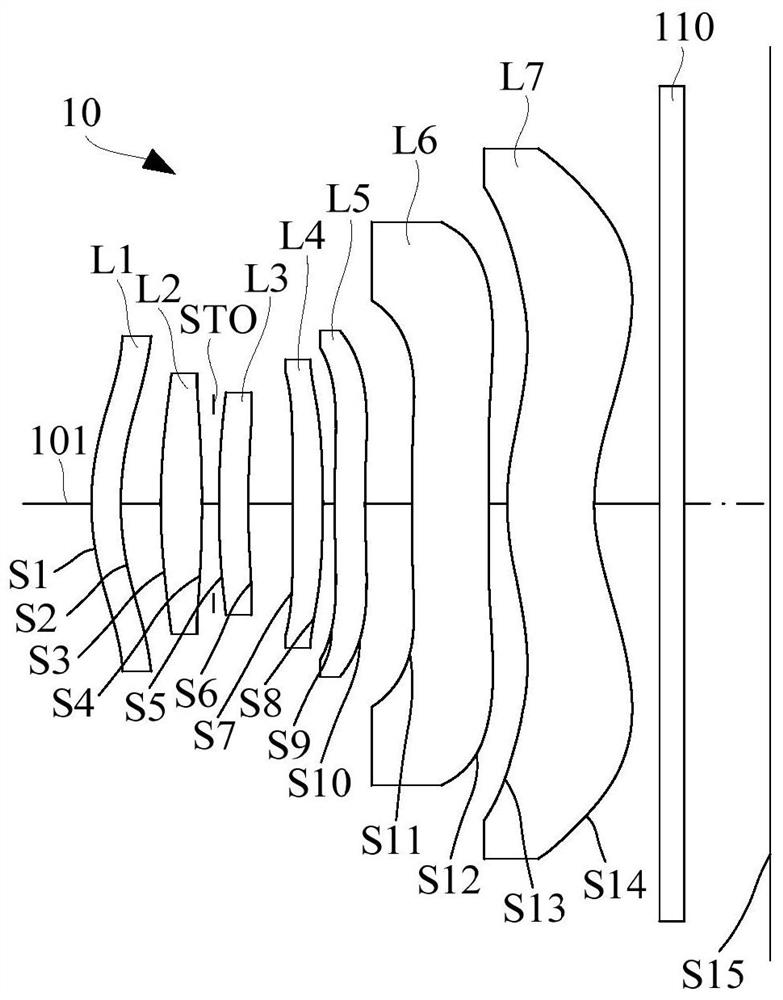
[0126] refer to Figure 5 , in the third embodiment, the optical system 10 includes a first lens L1 with negative refractive power, a second lens L2 with positive refractive power, an aperture stop STO, and a lens with positive refractive power from the object side to the image side along the optical axis 101. The third lens L3 with a refractive power, the fourth lens L4 with a positive refractive power, the fifth lens L5 with a negative refractive power, the sixth lens L6 with a positive refractive power, and the seventh lens L7 with a negative refractive power. Each lens surface type of optical system 10 is as follows:

[0127] The object side S1 of the first lens L1 is convex at the near optical axis, and the image side S2 is concave at the near optical axis; the object side S1 is convex near the maximum effective aperture, and the image side S2 is concave near the maximum effective aperture .

[0128] The object side S3 of the second lens L2 is convex at the near optical...


PUM

PropertyMeasurementUnit
Effective focal lengthaaaaaaaaaa
Optical lengthaaaaaaaaaa

Abstract

The invention relates to an optical system, a camera module and electronic equipment. The optical system includes: a first lens element having an object-side surface being convex in a paraxial place and an image-side surface being concave in a paraxial place; a second lens element with positive refractive power which has an object-side surface and an image-side surface being convex in a paraxial place; a third lens element having an object-side surface being convex in a paraxial place; a fourth lens element with positive refractive power having an image-side surface being convex in a paraxial place; a fifth lens element with negative refractive power having an object-side surface being convex in a paraxial place and an image-side surface being concave in a paraxial place; a sixth lens element with positive refractive power, the object-side and image-side surfaces thereof being convex in paraxial place; and a seventh lens element having an object-side surface being convex in a paraxial placeand an image-side surface being concave in a paraxial place. The optical system satisfies the following relation: TTL/d15 is more than 3.8 and less than 4.3, TTL is the total optical length, and d15 is the sum of the thicknesses of all the lenses from the first lens to the fifth lens on the optical axis. The optical system can achieve both miniaturization and good imaging quality.

Description

technical field [0001] The invention relates to the technical field of photography and imaging, in particular to an optical system, a camera module and electronic equipment. Background technique [0002] As the market demand for portable electronic devices such as smart phones, smart watches, and smart glasses increases significantly, how to further miniaturize portable electronic devices has become one of the focuses of the industry. One of the factors that mainly hinders the miniaturization of electronic equipment is that the various modules in the equipment occupy too large a size, which hinders the further reduction of the thickness of the equipment. Further, the camera module with multi-chip design is often a large-scale structure in the device, while traditional compression methods (such as reducing the number of lenses) can shorten the size of the camera module in the direction of the optical axis, but it often This leads to a decrease in image quality, making it dif...

Claims


Application Information

Patent Timeline
IPC IPC(8): G02B13/00G02B13/18
CPCG02B13/0045G02B13/18
Inventor 乐宇明蔡雄宇兰宾利赵迪
Owner TIANJIN OFILM OPTO ELECTRONICS CO LTD
Why Eureka
Try Eureka