imaging lens

A technology of imaging lens and imaging surface, applied in the field of imaging lens, can solve the problems of lens imaging quality reduction, low chromatic aberration, etc., and achieve the effect of high resolution, low chromatic aberration, and best imaging quality

Inactive Publication Date: 2016-01-13
三营超精密光电(晋城)有限公司
View PDF5 Cites 0 Cited by
  • Summary
  • Abstract
  • Description
  • Claims
  • Application Information

AI Technical Summary

Problems solved by technology

In order to obtain better imaging quality, the lens needs to meet: (1) high resolution; (2) low chromatic aberration; (3) long back convex (flangeback, FB), wherein, the long back convex system makes the designed lens The last lens can be kept away from the CMOS to avoid scratches and particles on the lens, which will reduce the image quality of the lens

Method used


Image

  • imaging lens
  • imaging lens
  • imaging lens

Examples


no. 1 example

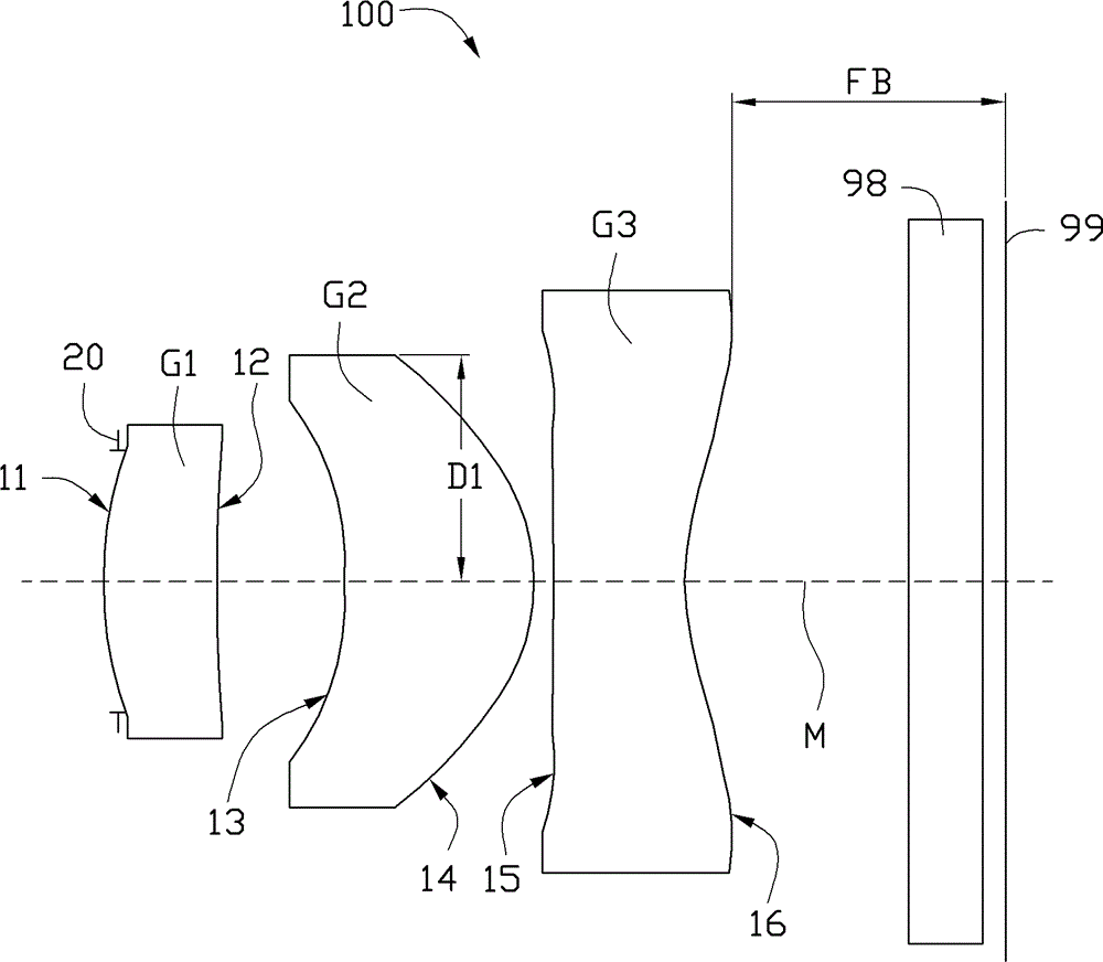
[0062] Each optical component of the imaging lens 100 provided by the first embodiment of the present invention satisfies the conditions in Table 1 and Table 2.

[0063] Table 1

[0064] optical surface

[0065] The object end surface of the third lens G3

[0066] Table 2

[0067]

[0068] table 3

[0069] F(mm)

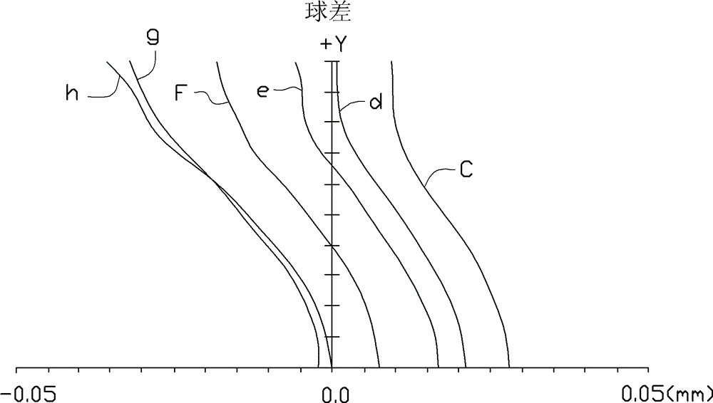
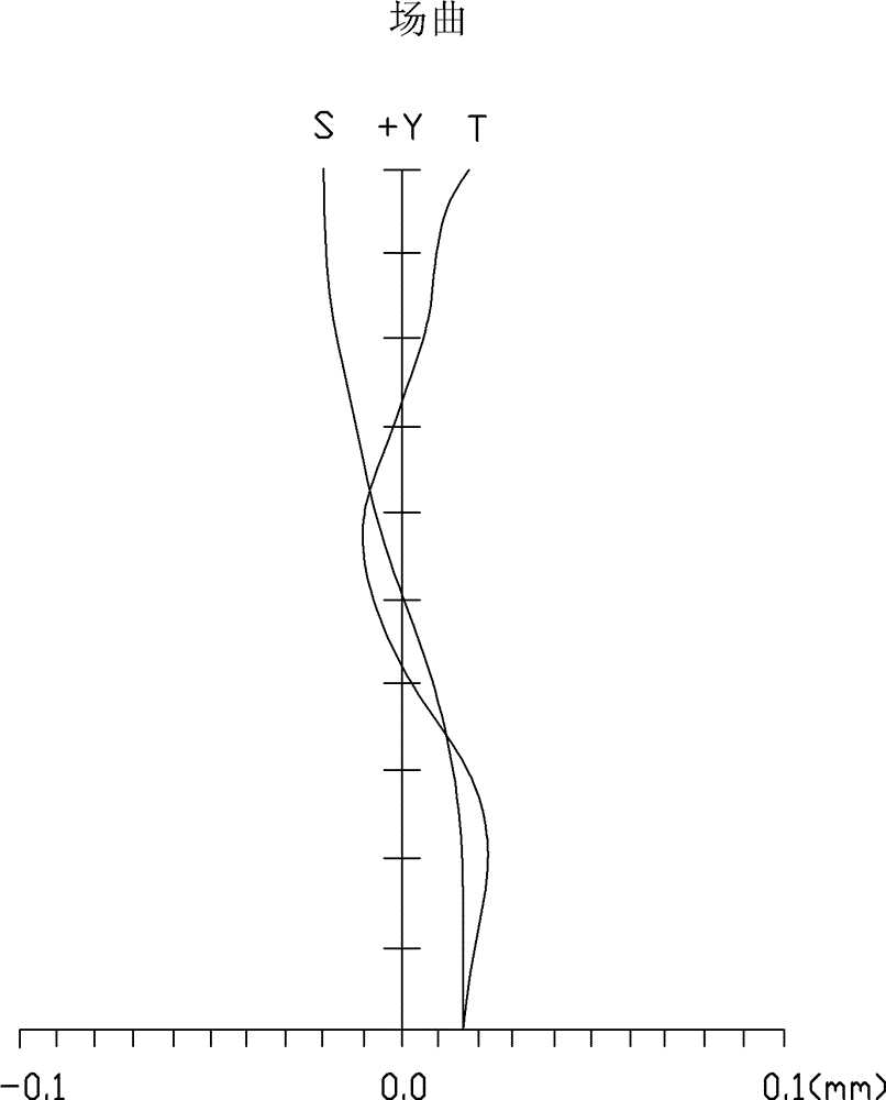
[0070] The spherical aberration, curvature of field, distortion, chromatic aberration, and MTF of the imaging lens 100 provided in this embodiment are respectively as follows Figure 2 to Figure 6 shown. specifically, figure 2 The six curves shown are for F-line (wavelength of 486.1 nanometers (nm)), d-line (wavelength of 587.6nm), C-line (wavelength of 656.3nm), e-line (wavelength of 546.1nm), g-line (wavelength is 435.8nm), h line (wavelength is 404.7nm) and the observed aberration value curve. It can be seen from the three curves that the aberration value generated by the imaging lens 100 of the first embodiment for visible l...

no. 2 example

[0072] Each optical component of the imaging lens 100 provided by the second embodiment of the present invention satisfies the conditions in Table 4, Table 5, and Table 6.

[0073] Table 4

[0074] optical surface

[0075] The object end surface of the filter 98

[0076] table 5

[0077]

[0078] Table 6

[0079] F(mm)

[0080] The spherical aberration, curvature of field, distortion, chromatic aberration, and MTF of the imaging lens 100 provided in this embodiment are respectively as follows Figure 7 to Figure 11 shown. specifically, Figure 7 The six curves shown are for F-line (wavelength of 486.1 nanometers (nm)), d-line (wavelength of 587.6nm), C-line (wavelength of 656.3nm), e-line (wavelength of 546.1nm), g-line (wavelength is 435.8nm), h line (wavelength is 404.7nm) and the observed aberration value curve. It can be seen from the three curves that the aberration value generated by the imaging lens 100 of the first embodiment for v...


PUM


Abstract

The invention provides an imaging lens. The imaging lens sequentially comprises a first lens with positive power, a second lens with positive power and a third lens with negative power from an object side to an image side; the first lens comprises a first surface and a second surface; the second lens comprises a third surface and a fourth surface; the third lens comprises a fifth surface and a sixth surface, wherein the imaging lens meets a relational expression that FB / TTL is more than 0.30, G1R2 / F1 is more than 19.54, and D1 / D2 is less than 1.62; and FB is the shortest distance between the sixth surface and an imaging surface in the direction of an optical axis, TTL is the overall length of the imaging lens, G1R2 is the curvature radius of the second surface, and F1 is the focal length of the first lens.

Description

technical field [0001] The invention relates to imaging technology, in particular to an imaging lens. Background technique [0002] With the improvement of the complementary metal oxide semiconductor (CMOS) production process, the size of a single pixel (PixelSize) in CMOS can be made smaller and smaller. The original 2.25μm is reduced to 1.75μm, and then further reduced to the currently commonly used 1.4μm. Correspondingly, the size of CMOS is also reduced from the original 1 / 4" (2.25μm) to 1 / 5" (1.75μm) ), and then further reduced to 1 / 6″ (1.4μm) commonly used at present. Due to the improvement of the process, a single wafer (Wafer) of the same size can be cut to obtain a larger number of grains (Die). Therefore, manufacturers It can effectively reduce the price of CMOS and increase product competitiveness. [0003] With the size of CMOS gradually shrinking, higher requirements are put forward for the design of the lens, so that the lens can match the CMOS with a smaller...

Claims


Application Information

Patent Timeline
Patent Type & Authority Patents(China)
IPC IPC(8): G02B13/18G02B13/00G02B13/22G02B1/00G02B5/20
Inventor 柯骏程
Owner 三营超精密光电(晋城)有限公司
Why Eureka
Try Eureka