Optical system, image capturing module, electronic device and driving device

A technology of optical system and optical axis, which is applied in the fields of electronic devices and driving devices, optical systems, and imaging modules, and can solve the problem of low pixel image quality of vehicle-mounted lenses

Pending Publication Date: 2021-03-16
TIANJIN OFILM OPTO ELECTRONICS CO LTD
View PDF0 Cites 0 Cited by
  • Summary
  • Abstract
  • Description
  • Claims
  • Application Information

AI Technical Summary

Problems solved by technology

[0004] Based on this, it is necessary to provide an improved optical system for the problem of low pixel image quality of traditional vehicle lens

Method used


Image

  • Optical system, image capturing module, electronic device and driving device
  • Optical system, image capturing module, electronic device and driving device
  • Optical system, image capturing module, electronic device and driving device

Examples


Embodiment 1

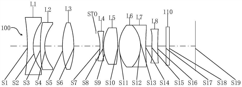
[0088] Refer to the following Figure 1 to Figure 2 The optical system 100 of Embodiment 1 of the present application will be described.

[0089] figure 1 A schematic structural diagram of the optical system 100 of Embodiment 1 is shown. Such as figure 1 As shown, the optical system 100 sequentially includes a first lens L1, a second lens L2, a third lens L3, a diaphragm STO, a fourth lens L4, a fifth lens L5, a sixth Lens L6, seventh lens L7, eighth lens L8 and imaging surface S19.

[0090] The first lens L1 has negative refractive power, and its object side S1 and image side S2 are both spherical surfaces, wherein the object side S1 is concave at the near optical axis, and the image side S2 is concave at the near optical axis.

[0091] The second lens L2 has a negative refractive power, and its object side S3 and image side S4 are both aspherical, wherein the object side S3 is convex at the near optical axis, and the image side S4 is concave at the near optical axis.

...

Embodiment 2

[0121] Refer to the following Figure 3 to Figure 4 The optical system 100 of Embodiment 2 of the present application will be described. In this embodiment, for the sake of brevity, descriptions similar to those in Embodiment 1 will be omitted.

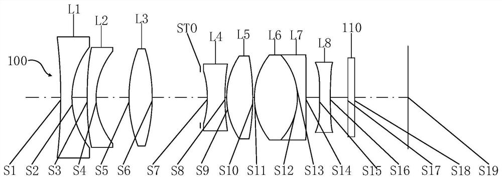
[0122] image 3 A schematic structural diagram of the optical system 100 of Embodiment 2 is shown. Such as image 3 As shown, the optical system 100 sequentially includes a first lens L1, a second lens L2, a third lens L3, a diaphragm STO, a fourth lens L4, a fifth lens L5, a sixth Lens L6, seventh lens L7, eighth lens L8 and imaging surface S19.

[0123] The first lens L1 has negative refractive power, and its object side S1 and image side S2 are both spherical surfaces, wherein the object side S1 is concave at the near optical axis, and the image side S2 is concave at the near optical axis.

[0124] The second lens L2 has a negative refractive power, and its object side S3 and image side S4 are both aspherical, wherein the obje...

Embodiment 3

[0140] Refer to the following Figure 5 to Figure 6 The optical system 100 of Embodiment 3 of the present application will be described. In this embodiment, for the sake of brevity, descriptions similar to those in Embodiment 1 will be omitted.

[0141] Figure 5 A schematic structural diagram of the optical system 100 of Embodiment 3 is shown. Such as Figure 5 As shown, the optical system 100 sequentially includes a first lens L1, a second lens L2, a third lens L3, a diaphragm STO, a fourth lens L4, a fifth lens L5, a sixth Lens L6, seventh lens L7, eighth lens L8 and imaging surface S19.

[0142] The first lens L1 has negative refractive power, and its object side S1 and image side S2 are both spherical surfaces, wherein the object side S1 is concave at the near optical axis, and the image side S2 is concave at the near optical axis.

[0143] The second lens L2 has a negative refractive power, and its object side S3 and image side S4 are both aspherical, wherein the ob...


PUM


Abstract

The invention provides an optical system, an image capturing module, an electronic device and a driving device. The optical system comprises, in order from an object side to an image side along an optical axis: a first lens element with negative refractive power, a second lens element with negative refractive power, a third lens element with positive refractive power, a diaphragm, a fourth lens element with negative refractive power, a fifth lens element with positive refractive power, a sixth lens element with positive refractive power, a seventh lens element with negative refractive power, and an eighth lens element with refractive power. The optical system can give consideration to the characteristics of high pixel, high image quality and miniaturization when a specific relationship issatisfied.

Description

technical field [0001] The invention relates to the technical field of optical imaging, in particular to an optical system, an imaging module, an electronic device and a driving device. Background technique [0002] In recent years, with the rise of surround-view cameras, ADAS (Advanced Driving Assistance System, Advanced Driver Assistance System) and unmanned driving markets, more and more vehicle-mounted lenses are used in automotive assisted driving systems. Among them, the front-view or side-view camera device can be used as a camera system in advanced driver assistance systems to analyze video content, realize lane departure warning (LDW), automatic lane keeping assist (LKA), high beam / low beam control and traffic control. Sign Recognition (TSR). [0003] However, traditional vehicle lens aberrations are difficult to correct effectively, and cannot capture the details of the subject well, so that the driving assistance system cannot accurately judge the environmental...

Claims


Application Information

Patent Timeline
IPC IPC(8): G02B13/00G02B13/06G02B13/18
CPCG02B13/0045G02B13/006G02B13/06G02B13/18
Inventor 杨懿
Owner TIANJIN OFILM OPTO ELECTRONICS CO LTD
Why Eureka
Try Eureka