imaging lens

A technology of imaging lens and imaging surface, which is applied in the field of imaging technology to achieve good aberration correction effect, proper distribution of optical power, and good image quality

Inactive Publication Date: 2017-02-08
三营超精密光电(晋城)有限公司
View PDF10 Cites 0 Cited by
  • Summary
  • Abstract
  • Description
  • Claims
  • Application Information

AI Technical Summary

Problems solved by technology

[0003] However, under the premise that the pixel size is reduced to 1.75 μm, the quality of the lens to be designed will need to be improved as the pixel size is reduced to meet the needs of users

Method used


Image

  • imaging lens
  • imaging lens
  • imaging lens

Examples


no. 1 approach

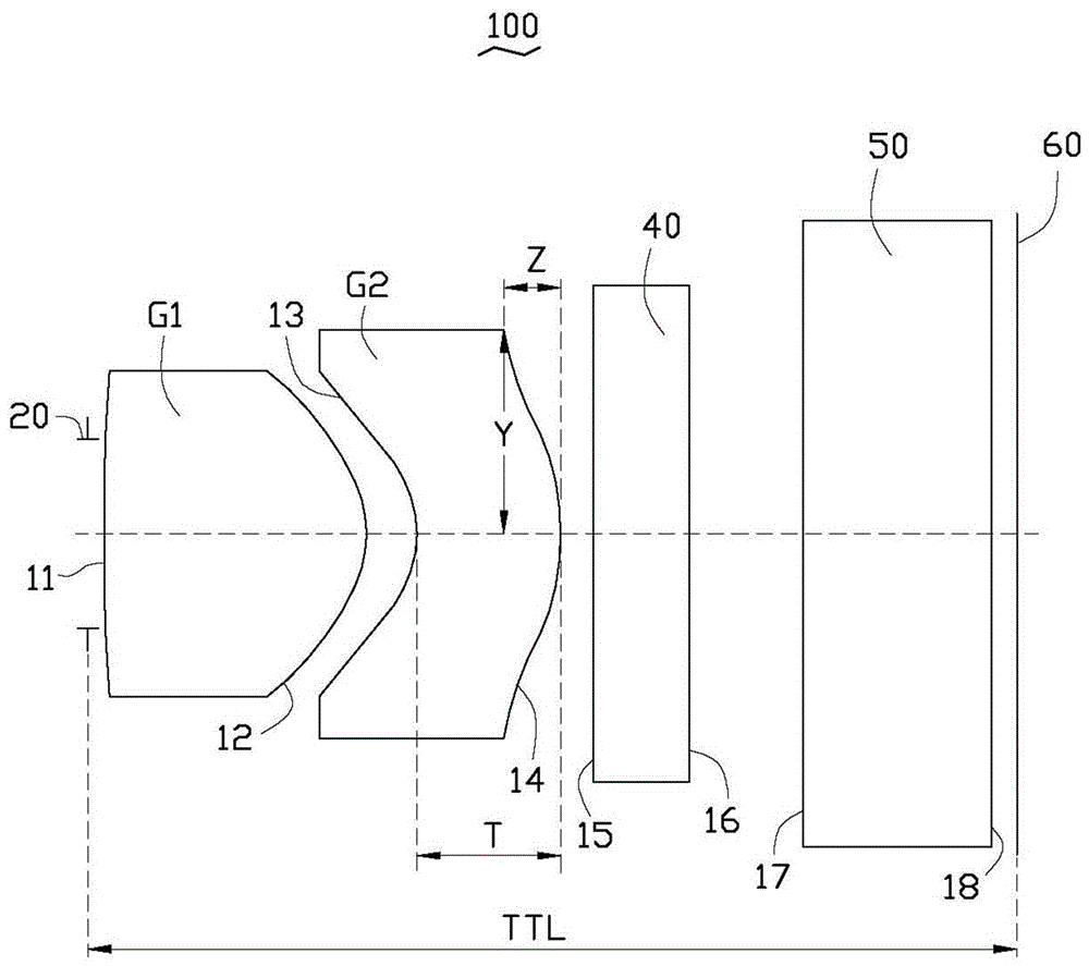
[0050] Each optical component of the imaging lens 100 provided by the first embodiment of the present invention satisfies the conditions in Tables 1 to 3.

[0051] Table 1

[0052] optical surface face shape ri(mm) Di(mm) ni vi the ki Aperture 20 flat gigantic 0.04 -- -- -- first surface 11 Aspherical 1.26 0.56 1.53 56.0 0 second surface 12 Aspherical -0.32 0.11 -- -- -1.88 third surface 13 Aspherical -0.20 0.30 1.58 31.0 -0.81 fourth surface 14 Aspherical -0.43 0.05 -- -- -2.75 fifth surface 15 flat gigantic 0.21 1.52 58.6 -- Sixth Surface 16 flat gigantic 0.25 -- -- -- Seventh Surface 17 flat gigantic 0.40 1.52 58.6 -- Eighth Surface 18 flat gigantic 0.05 -- -- -- Imaging surface 60 flat -- -- -- -- --

[0053] Table 2

[0054] Aspheric coefficient first surface 11 second surface 12 third surface 13 fourth su...

no. 2 approach

[0060] Each optical component of the imaging lens 100 provided by the second embodiment of the present invention satisfies the conditions in Table 4, Table 5, and Table 6.

[0061] Table 4

[0062] optical surface face shape ri(mm) Di(mm) ni vi the ki Aperture 20 flat gigantic 0.04 -- -- -- first surface 11 Aspherical 1.31 0.55 1.53 56.0 -1.50 second surface 12 Aspherical -0.31 0.12 -- -- -1.73 third surface 13 Aspherical -0.19 0.30 1.58 31.0 -0.83 fourth surface 14 Aspherical -0.42 0.05 -- -- -2.32 fifth surface 15 flat gigantic 0.21 1.52 58.6 -- Sixth Surface 16 flat gigantic 0.25 -- -- -- Seventh Surface 17 flat gigantic 0.40 1.52 58.6 -- Eighth Surface 18 flat gigantic 0.05 -- -- -- Imaging surface 60 flat -- -- -- -- --

[0063] table 5

[0064] Aspheric coefficient first surface 11 second surface 12 third s...


PUM


Abstract

An imaging lens sequentially comprises a first lens body, a second lens body and an imaging surface from an object side to an image side, wherein the first lens body is provided with positive optical power, and the second lens body is provided with negative optical power. The first lens body comprises a first surface and a second surface, and the second lens body comprises a third surface and a fourth surface. The imaging lens meets the following requirements: FB / TTL>0.38, R11 / F1>2.23, Z / Y>0.11, Z / T<0.42, and R23 / F2<R12 / F2<R24 / F2, wherein FB is the shortest distance between the fourth surface and the imaging surface along the direction of the optical axis, TTL is the overall length of the imaging lens, R11 is the radius of curvature of the first surface, F1 is the focal distance of the first lens body, Z is the transverse height of a curved surface of the fourth surface, Y is the longitudinal height of the curved surface of the fourth surface, T is the thickness of the second lens body on the optical axis, R23 is the radius of curvature of the third surface, R24 is the radius of curvature of the fourth surface, R12 is the radius of curvature of the second surface, and F2 is the focal distance of the second lens body.

Description

technical field [0001] The invention relates to an imaging technology, in particular to an imaging lens. Background technique [0002] With the improvement of CMOS process technology, imaging lens products with the same pixels, such as VGA specifications with a screen resolution of 640*480, have a total pixel of about 300,000 pixels (0.3M Pixels), because the pixel size of a CMOS image sensor (Pixel Size) can be effectively reduced, from the current 3.6 μm to 2.2 μm, and then to the current 1.75 μm that can be mass-produced. Therefore, the size of the CMOS image sensor is also reduced from 1 / 6” (corresponding to the pixel size 3.6μm) to 1 / 10" (corresponding to a pixel size of 2.2μm), and then to the current 1 / 13" (corresponding to a pixel size of 1.75μm). This makes products with the same pixel, because the wafer (Wafer) can be cut out Die increases, so the cost of CMOS image sensors can be effectively reduced, increasing product competitiveness. [0003] However, under th...

Claims


Application Information

Patent Timeline
Patent Type & Authority Patents(China)
IPC IPC(8): G02B13/18G02B13/00G02B7/00
Inventor 柯骏程
Owner 三营超精密光电(晋城)有限公司
Why Eureka
Try Eureka