
Check valve

A technology of check valve and valve body, which is applied in the direction of lifting valve, valve details, control valve, etc., can solve the problems of affecting the working process, insufficient sensitivity of blade rotation, and consumption of fluid flow energy, etc., to achieve the effect of reducing energy consumption

Active Publication Date: 2021-08-17
SICHUAN CHENGDU AIR SEPERATION PLANT VALVE
View PDF13 Cites 0 Cited by
  • Summary
  • Abstract
  • Description
  • Claims
  • Application Information

AI Technical Summary

Problems solved by technology

[0003] The current check valve generally has the following problems: in the pipeline with low fluid pressure, the valve flap cannot be completely closed due to the low fluid pressure, so the fluid can still flow backwards, thus affecting the working process
[0005] 1. Since the drive shaft of the driving vane is installed along the axial direction of the valve body, when the liquid level in the pipeline is low and the fluid pressure is low, the rotation of the vane is not sensitive enough, so that the force of the vane on the sealing film is small or Virtually no force, fluid backflow is still possible
[0006] 2. When the fluid is flowing forward, the blades will continue to rotate under the action of the fluid, which will consume the energy of the fluid flow and cause a waste of energy

Method used


Image

  • Check valve
  • Check valve
  • Check valve

Examples


Embodiment Construction

[0036] In the following, only some exemplary embodiments are briefly described. As those skilled in the art would realize, the described embodiments may be modified in various different ways, all without departing from the spirit or scope of the present invention. Accordingly, the drawings and descriptions are to be regarded as illustrative in nature and not restrictive.

[0037] In the description of the embodiments of the present invention, it should be understood that the terms "lateral", "length", "width", "left", "right", "horizontal", "inner", "outer", "clockwise ", "counterclockwise", "axial", "circumferential", etc. indicate the orientation or positional relationship based on the orientation or positional relationship shown in the drawings, and are only for the convenience of describing the embodiment of the present invention and simplifying the description, rather than Nothing indicating or implying that a referenced device or element must have a particular orientati...


PUM


Abstract

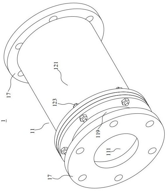
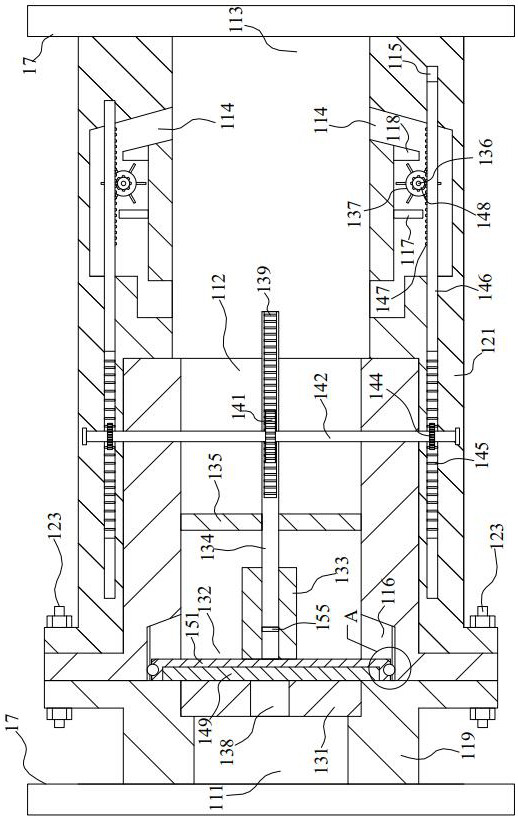
The invention provides a check valve, and relates to the technical field of valves. The check valve comprises a valve body and a valve element mechanism, wherein the valve body is provided with an inlet end, a connecting channel and an outlet end which are sequentially connected; the valve element mechanism comprises a flow limiting plate, a sealing assembly, a connecting sleeve, a movable rod, a supporting plate, rotating shafts and blades; the flow limiting plate is fixed in the connecting channel; a flow limiting hole is formed in the middle of the flow limiting plate; the sealing assembly is arranged on one side of the flow limiting plate; the connecting sleeve is installed on one side of the sealing assembly, and connected with the movable rod in an insertion mode; the supporting plate is fixed in the connecting channel; fluid can flow through the supporting plate; one end of the movable rod is connected with the supporting plate in an insertion mode; flow guide channels are formed in the side walls of the valve body; and the blades are installed in the flow guide channels through the rotating shafts, and are in transmission connection with the movable rod. When the fluid flows reversely, the situation that the fluid flows reversely can be better avoided through the sealing assembly; and when the fluid flows in the forward direction, the blades are prevented from rotating under the action of the fluid all the time, so that energy consumption is reduced.

Description

technical field [0001] The invention relates to the technical field of valves, in particular to a check valve. Background technique [0002] Check valve, also known as one-way valve or check valve, its function is to prevent the medium in the pipeline from flowing backward, that is, when the fluid flows in the opposite direction, under the action of fluid pressure, the disc of the one-way valve is closed, so that the fluid Can not flow backwards. [0003] The current check valve generally has the following problems: in the pipeline with low fluid pressure, the valve disc cannot be completely closed due to the low fluid pressure, so that the fluid can still flow backwards, thereby affecting the working process. [0004] The Chinese invention patent with the publication number CN112361040A discloses a check valve. Although it can solve the above problems to a certain extent, there are still the following problems to be solved urgently: [0005] 1. Since the drive shaft of th...

Claims


Application Information

Patent Timeline
IPC IPC(8): F16K15/02F16K1/32F16K1/36F16K31/53F16K1/46F16K47/00
CPCF16K1/32F16K1/36F16K1/46F16K15/023F16K31/53F16K47/00
Inventor 杨增伟秦雄飞丁杭利
Owner SICHUAN CHENGDU AIR SEPERATION PLANT VALVE
Learn More