
Ultrasonic wall thickness on-line monitoring device for oil and gas pipeline

A technology for oil and gas pipelines and monitoring devices, which is applied to measuring devices, using ultrasonic/sonic/infrasonic waves, instruments, etc., to solve the problem of inability to achieve continuous and dead-end pipeline wall thickness scanning, inability to achieve long-distance continuous pipeline scanning, large time and labor costs

Active Publication Date: 2021-08-17
CHINA UNIV OF PETROLEUM (BEIJING)
View PDF8 Cites 3 Cited by
  • Summary
  • Abstract
  • Description
  • Claims
  • Application Information

AI Technical Summary

Problems solved by technology

[0004] Most of the existing disclosed ultrasonic thickness measurement equipment can only perform fixed-point thickness measurement, and the scanning range is limited to the fixed position of each ultrasonic probe, which cannot realize continuous and dead-angle-free pipe wall thickness scanning
For areas that cannot be scanned, manual on-site ultrasonic scanning is required to supplement, resulting in large time and labor costs
A few published ultrasonic thickness measuring equipment can realize the non-dead angle scanning in the circumferential direction of the pipeline, but cannot realize the long-distance continuous scanning in the axial direction of the pipeline

Method used


Image

  • Ultrasonic wall thickness on-line monitoring device for oil and gas pipeline
  • Ultrasonic wall thickness on-line monitoring device for oil and gas pipeline
  • Ultrasonic wall thickness on-line monitoring device for oil and gas pipeline

Examples


Embodiment Construction

[0047] In order to have a clearer understanding of the technical features, purposes and effects of the present invention, the specific implementation manners of the present invention will now be described with reference to the accompanying drawings.

[0048]The specific implementations of the present invention described here are only for the purpose of explaining the present invention, and should not be construed as limiting the present invention in any way. Under the teaching of the present invention, the skilled person can conceive any possible modification based on the present invention, and these should be regarded as belonging to the scope of the present invention. It should be noted that when an element is referred to as being “disposed on” another element, it may be directly on the other element or there may also be an intervening element. When an element is referred to as being "connected to" another element, it can be directly connected to the other element or interve...


PUM


Abstract

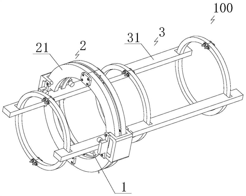
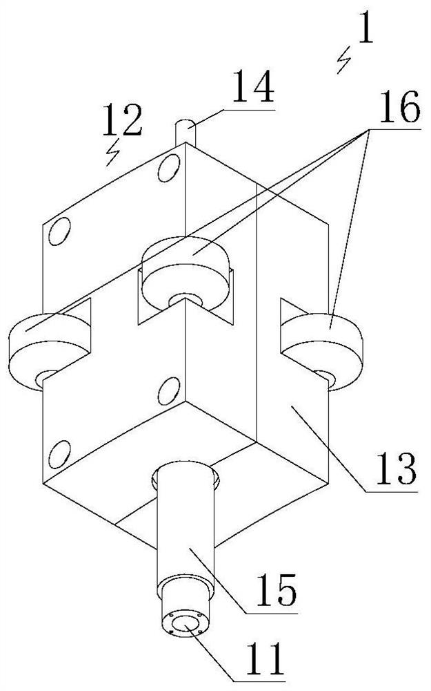
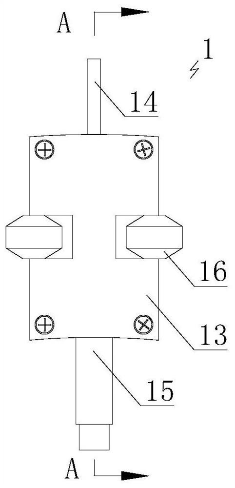
The invention relates to an ultrasonic wall thickness on-line monitoring device for an oil and gas pipeline, which comprises a probe structure for on-line monitoring of the wall thickness of the oil and gas pipeline and comprising an ultrasonic probe which can be telescopically connected to a probe bracket along the radial direction of the pipeline; a guide structure, comprising a circumferential guide rail structure and an axial guide rail structure, the circumferential guide rail structure comprising a first guide rail, and the probe support can rotate in the circumferential direction of the first guide rail to change the circumferential position of the ultrasonic probe; the axial guide rail structure comprising a second guide rail, the second guide rail is axially arranged along the pipeline, and the circumferential guide rail structure can move along the second guide rail to change the axial position of the ultrasonic probe; a control part, used for receiving and transmitting ultrasonic signals, receiving and processing monitoring data of the ultrasonic probe and electrically controlling the probe structure and the guide structure, and the probe structure and the guide structure being electrically connected with the control part. The device has multi-point monitoring capability, axial full-pipe-length monitoring capability and circumferential 360-degree monitoring capability, and can realize on-line monitoring of variable-pipe-diameter wall thickness.

Description

technical field [0001] The invention relates to the technical field of ultrasonic monitoring in the petroleum and petrochemical industry, in particular to an ultrasonic wall thickness online monitoring device for oil and gas pipelines. Background technique [0002] The petroleum and petrochemical industry has a large number of oil and gas pipelines, widely distributed, various corrosion factors, and complex laying environment. With the increase of the service life, there are greater risks and hidden dangers. Especially in recent years, oil and gas pipelines have been affected by third-party damage and natural geological disasters, which have caused serious losses and potentially huge damage to the safe and stable operation of pipelines. Therefore, it is necessary to monitor the wall thickness reduction status of oil and gas pipelines in key areas. [0003] The existing ultrasonic thickness measurement system generally uses brackets and clamps to arrange multiple ultrasonic ...

Claims


Application Information

Patent Timeline
Patent Type & Authority Applications(China)
IPC IPC(8): G01B17/02
CPCG01B17/02
Inventor 贾晓丽姚宁张行董绍华李德华许博郑磊
Owner CHINA UNIV OF PETROLEUM (BEIJING)
Learn More