
Light emitting parameter adjusting method and device, storage medium and electronic device

An adjustment method and parameter technology, which is applied in the electronic field, can solve the problems of low adjustment efficiency of luminescence parameters, and achieve the effect of improving adjustment efficiency

Active Publication Date: 2021-08-24
ZHEJIANG DAHUA TECH CO LTD
View PDF11 Cites 4 Cited by
  • Summary
  • Abstract
  • Description
  • Claims
  • Application Information

AI Technical Summary

Problems solved by technology

[0004] The embodiment of the present invention provides a method, device, storage medium and electronic device for adjusting luminous parameters, so as to at least solve the problem of splicing the display device in the related art The problem of low efficiency in the adjustment of the luminescence parameters

Method used


Image

  • Light emitting parameter adjusting method and device, storage medium and electronic device
  • Light emitting parameter adjusting method and device, storage medium and electronic device
  • Light emitting parameter adjusting method and device, storage medium and electronic device

Examples


Embodiment Construction

[0026] Embodiments of the present invention will be described in detail below with reference to the drawings and in combination with the embodiments.

[0027] It should be noted that the terms "first" and "second" in the description and claims of the present invention and the above drawings are used to distinguish similar objects, but not necessarily used to describe a specific sequence or sequence.

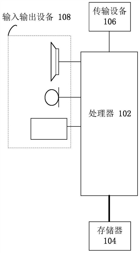
[0028] The method embodiments provided in the embodiments of the present application may be executed in mobile terminals, computer terminals or similar computing devices. Taking running on a mobile terminal as an example, figure 1 It is a block diagram of the hardware structure of the mobile terminal of the method for adjusting the light emission parameters in the embodiment of the present invention. Such as figure 1 As shown, the mobile terminal may include one or more ( figure 1 Only one is shown in the figure) processor 102 (processor 102 may include but not limited to a pr...


PUM


Abstract

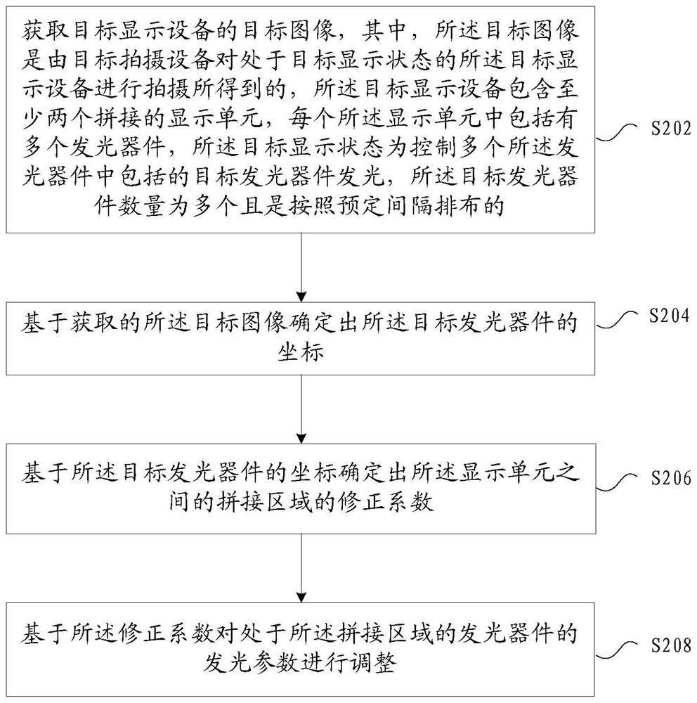
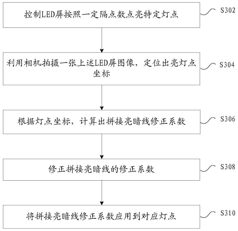
The embodiment of the invention provides a light-emitting parameter adjusting method and device, a storage medium and an electronic device. The method comprises the steps: acquiring a target image of target display equipment, wherein the target image is obtained by shooting the target display equipment in a target display state, the target display equipment comprises at least two spliced display units, each display unit comprises a plurality of light-emitting devices, and the target display state is to control target light-emitting devices arranged according to a preset interval in the plurality of light-emitting devices to emit light; determining coordinates of a target light-emitting device based on the acquired target image; determining a correction coefficient of a splicing area between the display units based on the coordinates of the target light-emitting device; and adjusting a light emitting parameter of the light emitting device in the splicing area based on the correction coefficient. Through the method and the device, the problem of low adjustment efficiency of the light-emitting parameters of the splicing area of the display equipment in the prior art is solved, and the effect of improving the adjustment efficiency is achieved.

Description

technical field [0001] Embodiments of the present invention relate to the field of electronic technology, and in particular, relate to a method, device, storage medium, and electronic device for adjusting light emission parameters. Background technique [0002] The LED display screen can be spliced ​​by several LED cabinets or LED display modules (here collectively referred to as display units) according to factors such as the environment. Each display unit can be calibrated in the factory to ensure that the LED display when leaving the factory The uniformity of brightness and chromaticity is good, but in the process of splicing, due to the limitations of machining precision, assembly accuracy and other technological reasons, there will be uneven splicing between display units, resulting in LED lights on the adjacent edges on both sides of the splicing. The distance between them may be greater or smaller than the distance between the light points in the display unit. At this...

Claims


Application Information

Patent Timeline
Patent Type & Authority Applications(China)
IPC IPC(8): G09G3/32
CPCG09G3/32
Inventor 刘硕刘晓沐王松俞克强朱国卿张晴晴涂永亮
Owner ZHEJIANG DAHUA TECH CO LTD
Learn More