
Patsnap Eureka
For R&D, Patsnap Eureka makes reading and utilizing patents & technical documents easy.
Patsnap Eureka AIR
Designed for self-driven R&D workflows. Generate viable solutions, solve complex R&D challenges, empower your innovation with AI.

Patsnap Eureka Materials
Designed for material experts only. Revolutionize your material R&D, from search, analyze, to developing new materials.

TechResearch
Generate reliable direction feasibility study reports for your R&D in just a few steps.

TechSeek
Discover and master advanced knowledge NOW. Basics, ideas, possibilities, all at once.

TechMind
As an expert in R&D Theories, TechMind can generates customized viable solutions instantly.

TechRisk
Analyze your overall solution with one click, know your potential R&D risks in advance.

TechMonitor
Get weekly tech updates, stay abreast of the latest tech innovations and key insights.
Hollow iron core
A technology of hollow iron core and solid iron core, applied in the direction of magnetic core/yoke, transformer/inductor magnetic core, electrical components, etc., can solve the problems of high cost and heavy weight of iron core
- Summary
- Abstract
- Description
- Claims
- Application Information
AI Technical Summary
Problems solved by technology
Method used
Image

Examples
Embodiment 1
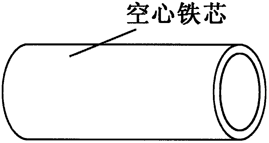
[0021] The hollow iron core of the patent of the present invention includes the hollow iron core used to increase the induced current. The cross section of the hollow iron core can be in various shapes that are not solid. In the illustration of this embodiment—— figure 1 Among them, the cross-section of the hollow iron core is annular. Hollow core is not limited to figure 1 Shown as a straight cylinder, the hollow iron core can be in various shapes like the solid iron core.
[0022] Specifically, the wire (1) with the insulating layer is wound on the outer surface of the hollow iron core, and the wire (1) is connected to the power supply; the wire (2) with the insulating layer is wound on the outer surface of the hollow iron core, and the wire (1) is connected to the power supply; (2) Connect electrical appliances or instruments, wires (2) or connect electrical appliances and instruments at the same time; when there is a changing current in the wire (1) loop, there is an indu...
Embodiment 2
[0026] Wrap the wire (1) with an insulating layer on the outer surface of the hollow iron core, and connect the wire (1) to the power supply; form a closed loop with the wire (2) with an insulating layer on the left or right side of the hollow iron core, The wire (2) is connected to the electrical appliance or the instrument, and the wire (2) is connected to the electrical appliance and the instrument at the same time; when there is a changing current in the wire (1) loop, an induced current is displayed in the wire (2) loop.
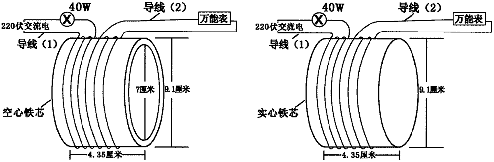
[0027] I did the following application experiments: image 3 As shown, the section of the hollow iron core is a ring, the outer diameter of the ring is 9.1 centimeters, the inner diameter is 7 centimeters, and the length of the iron core is 4.35 centimeters. The wire (1) with an insulating layer is tightly wound on the outer surface of the hollow iron core for 5 The wire (1) is connected to the power supply and a 40W light bulb; the wire (2) with an ins...
Embodiment 3
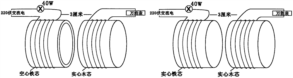
[0032] Such as Figure 4 As shown, the wires closely wound on the outer surfaces of two identical hollow cylindrical iron cores are the same. The outer diameter of the hollow iron core is 9.1 cm, the inner diameter is 7 cm, and the height of the hollow iron core is 8 cm. Directly above an iron core with densely wound wires, two hollow iron cores are 0.5 cm apart, and the wall thickness of the iron cores is uniform; the wires wound around the two hollow iron cores pass such a current: If the two hollow iron cores are solid , when electrifying the wires tightly wound around the two iron cores, if one of the two adjacent ends of the two iron cores is an S pole, the other is an N pole; At this time, the electrons -q near the two adjacent iron core walls can be accelerated due to the induced electric field, so that an electron betatron can be made.
PUM
| Property | Measurement | Unit |
|---|---|---|
| Outer diameter | aaaaa | aaaaa |
| The inside diameter of | aaaaa | aaaaa |
Abstract
Description
Claims
Application Information
 - R&D Engineer
- R&D Manager
- IP Professional
- Industry Leading Data Capabilities
- Powerful AI technology
- Patent DNA Extraction
Browse by: Latest US Patents, China's latest patents, Technical Efficacy Thesaurus, Application Domain, Technology Topic, Popular Technical Reports.
© 2024 PatSnap. All rights reserved.Legal|Privacy policy|Modern Slavery Act Transparency Statement|Sitemap|About US| Contact US: help@patsnap.com