Tank gun aiming shooting method and device

A technology for aiming and shooting, tank guns, applied in aiming devices, guidance methods, weapon accessories, etc., can solve the problems of time-consuming, inability to guarantee the accuracy of aiming and shooting, unfavorable aiming and shooting, etc., to simplify the structure, reduce the aiming and shooting process, The effect of improving the accuracy of shooting aiming

Active Publication Date: 2021-08-27
中国人民解放军68302部队参谋部
View PDF5 Cites 3 Cited by
  • Summary
  • Abstract
  • Description
  • Claims
  • Application Information

AI Technical Summary

Problems solved by technology

[0004] The technical problem to be solved by the present invention is that when the tank gun uses the "two-line intersection mode" for aiming and shooting, it is easily affected by the environment and the state of travel and cannot guarantee the accuracy of aiming and shooting, and the existing tank gun must be calibrated with the help of a special Ancillary equipment, time-consuming to operate, not conducive to aiming and shooting in emergency situations

Method used


Image

  • Tank gun aiming shooting method and device
  • Tank gun aiming shooting method and device
  • Tank gun aiming shooting method and device

Examples


Embodiment 1

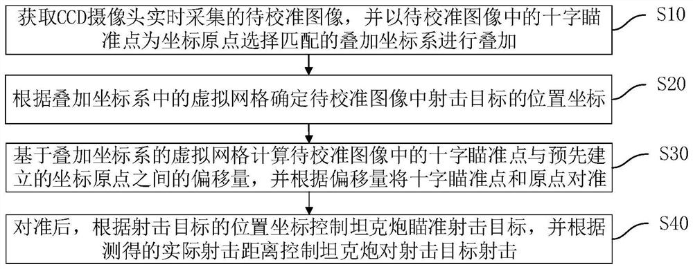
[0043] Such as figure 1 As shown, the present embodiment provides a tank gun aiming shooting method, comprising:

[0044] S10: Obtain the image to be calibrated collected by the CCD camera in real time, and select a matching superimposed coordinate system with the crosshair point in the image to be calibrated as the coordinate origin for superposition.

[0045] Among them, the image to be calibrated refers to the frame image obtained by dividing the image or video captured by the CCD camera in real time when the tank gun is aimed at the target.

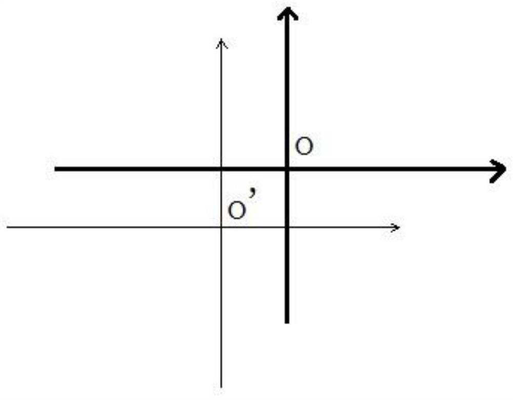
[0046] Specifically, the direction of the horizontal axis of the superimposed coordinate system in this embodiment is parallel to the earth, and the direction of the vertical axis is perpendicular to the earth.

[0047] S20: Determine the position coordinates of the shooting target in the image to be calibrated according to the virtual grid in the superimposed coordinate system.

[0048] In this embodiment, the size and shape of eac...

Embodiment 2

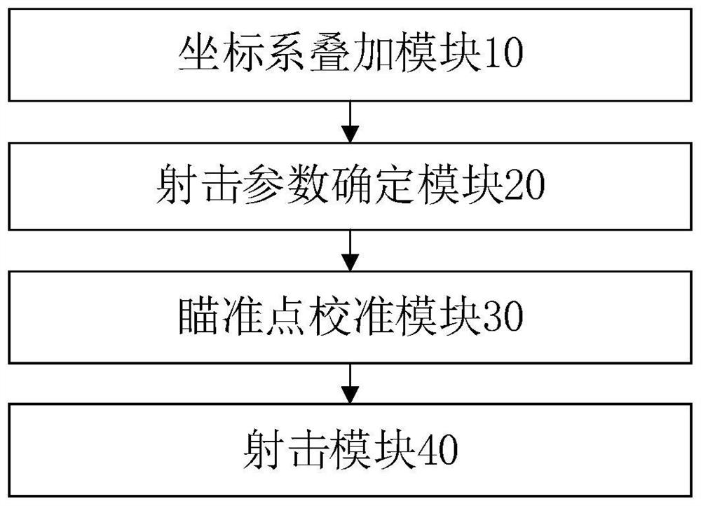
[0072] Such as image 3 As shown, the present embodiment provides a tank gun aiming device corresponding to the tank gun aiming method in Embodiment 1, including:

[0073] The coordinate system superimposition module 10 is used to obtain the image to be calibrated collected by the CCD camera in real time, and select a matching superimposition coordinate system with the cross aiming point in the image to be calibrated as the coordinate origin for superposition.

[0074] The shooting parameter determination module 20 is configured to determine the position coordinates of the shooting target in the image to be calibrated according to the virtual grid in the superimposed coordinate system.

[0075] The aiming point calibration module 30 is used to calculate the offset between the cross aiming point in the image to be calibrated and the pre-established coordinate origin based on the virtual grid of the superimposed coordinate system, and align the cross aiming point and the origin ...


PUM


Abstract

The invention discloses a tank gun aiming shooting method and device. A cross aiming point in a to-be-calibrated image is taken as a coordinate origin, a matched superposition coordinate system is selected for superposition, position coordinates of a shooting target in the to-be-calibrated image are determined according to virtual grids in the superposition coordinate system, then the offset between the cross aiming point in the to-be-calibrated image and a pre-established coordinate origin is calculated based on the virtual grids of the superposition coordinate system, the cross aiming point is aligned with the origin according to the offset, after alignment, a tank gun is controlled to aim at the shooting target according to the position coordinates of the shooting target, the tank gun is controlled to shoot the shooting target according to the measured actual shooting distance, so that the tank gun does not need to be provided with a sighting telescope, the structure is simplified, the aiming shooting process is reduced, and the shooting aiming accuracy of the tank gun is improved.

Description

technical field [0001] The invention relates to the technical field of aiming and shooting of tank guns, in particular to a method and device for aiming and shooting of tank guns. Background technique [0002] Restricted by factors such as the firing principle of tank guns and the operating mechanism of their parts, the "three-point-one-line" mode of conventional weapons or the coincidence mode of the aiming line and the shooting line (aiming from the shooting direction or directly behind the shooting line) cannot be used for tank gun shooting and aiming. ), the mode of intersection of the sight line and the firing line is generally adopted at present, that is, the "two-line intersection" mode. [0003] However, the tank gun adopts the "two-line intersection mode" for aiming and shooting, and there are the following problems: 1. During the moving process of the tank, due to the bumping of the vehicle body, the shaking range of the observer and the scope is inconsistent, resu...

Claims


Application Information

Patent Timeline
Patent Type & Authority Applications(China)
IPC IPC(8): F41G1/46F41G3/30
CPCF41G1/46F41G3/30
Inventor 张宇隆王立峰王庆波张鲁阳
Owner 中国人民解放军68302部队参谋部
Why Eureka
Try Eureka