Shaft part machining clamp

A technology of shaft parts and fixtures, which is applied in the direction of manufacturing tools, metal processing equipment, metal processing machinery parts, etc., can solve the problems of waste equipment capacity, long processing interval, low processing efficiency, etc., to avoid waste, improve work efficiency, The effect of stable processing

Pending Publication Date: 2021-08-31
CHENGDU UNIVERSITY OF TECHNOLOGY
View PDF0 Cites 2 Cited by
  • Summary
  • Abstract
  • Description
  • Claims
  • Application Information

AI Technical Summary

Problems solved by technology

[0003] However, when processing shaft parts on existing lathes, when processing to the vicinity of the fixed end, due to the fixed section of the fixed caliper, it is necessary to loosen the caliper, and then manually or mechanically assist to turn the shaft to be processed, resulting in a longer processing interval. Waste equipment capacity, and after turning the unprocessed section close to the caliper to the other end, it is necessary to reposition the machining centerline of the shaft, resulting in low machining efficiency

Method used


Image

  • Shaft part machining clamp
  • Shaft part machining clamp
  • Shaft part machining clamp

Examples


Embodiment Construction

[0033] The following will clearly and completely describe the technical solutions in the embodiments of the present invention with reference to the drawings in the embodiments of the present invention. The embodiments described below by referring to the figures are exemplary only for explaining the present invention and should not be construed as limiting the present invention.

[0034] The embodiments of the present invention will be described below according to the overall structure of the present invention.

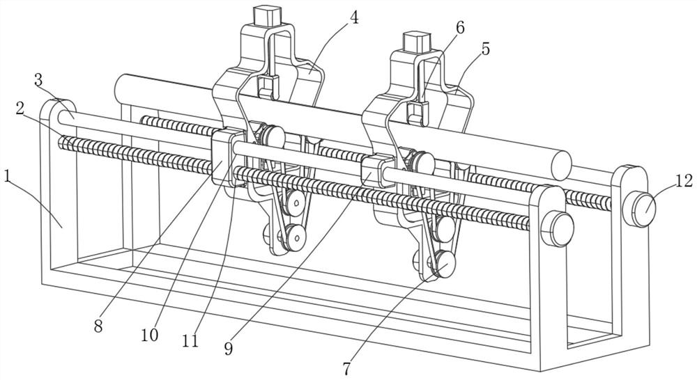
[0035] A machining fixture for shaft parts, such as Figure 1-8 As shown, including the installation base 1, the inner two ends of the installation base 1 are provided with screw rods 2 and polished rods 3, and the installation base 1 is respectively threaded with the first installation frame 4 and the second installation frame 5 through two sets of screw rods 2. 2 and the polished rod 3 install the first mounting frame 4 and the second mounting frame 5, so that the f...


PUM


Abstract

The invention discloses a shaft part machining clamp, and relates to the technical field of shaft clamps. The shaft part machining clamp comprises a mounting base, screw rods and polished rods are arranged at the two ends of the inner side of the mounting base, and the mounting base is in threaded connection with a first mounting frame and a second mounting frame through two sets of screw rods respectively. When the shaft part machining clamp is used, two sets of rotary supporting wheels are used for pre-supporting a part, then the supporting wheels are pushed till the supporting wheels make contact with a shaft part, and the supporting wheels are combined with the other two sets of rotary supporting wheels to form a triangular stable structure, so that the shaft part is firmly clamped, when a clamped part needs to be machined, only two sets of mutually matched electric rollers need to be pushed at the same time, the part is supported from the position under the part till the part is completely separated from the two sets of rotary supporting wheels, then the electric rollers are started, the part is driven to move horizontally, and the part is clamped after an original clamping section is exposed, so that time waste caused by re-clamping is avoided.

Description

technical field [0001] The invention relates to the technical field of shaft fixtures, in particular to a machining fixture for shaft parts. Background technique [0002] Fixtures are also called fixtures. In a broad sense, in any process in the process, the device used to install the workpiece quickly, conveniently and safely can be called a fixture. When processing the workpiece, in order to make the surface of the workpiece reach the drawing The specified size, geometric shape, and other technical requirements such as position accuracy with other surfaces, the workpiece must be positioned, clamped, and clamped before processing. [0003] However, when processing shaft parts on existing lathes, when processing to the vicinity of the fixed end, due to the fixed section of the fixed caliper, it is necessary to loosen the caliper, and then manually or mechanically assist to turn the shaft to be processed, resulting in a longer processing interval. The production capacity of ...

Claims


Application Information

Patent Timeline
Patent Type & Authority Applications(China)
IPC IPC(8): B23Q3/00B23Q1/72
CPCB23Q1/72B23Q3/00B23Q2703/10B23Q2703/12
Inventor 杜忠齐丁从张官杨安碧川陈星
Owner CHENGDU UNIVERSITY OF TECHNOLOGY
Why Eureka
Try Eureka