Underground water pressure reduction drainage device

A drainage device and groundwater technology, which is applied in construction, infrastructure engineering, etc., can solve problems such as potential safety hazards, high cost of passive anti-floating methods, and impact of building anti-floating structures

Inactive Publication Date: 2021-08-31
HEBEI UNIV OF ENG
View PDF0 Cites 0 Cited by
  • Summary
  • Abstract
  • Description
  • Claims
  • Application Information

AI Technical Summary

Problems solved by technology

[0002] In recent years, with the development of cities, people pay more and more attention to underground drainage facilities. At present, some underground structures in cities have no balance between upper load and buoyancy. When there is a lot of rain, the rise of groundwater level will affect the anti-floating structure of buildings. The existing anti-floating methods include passive anti-floating methods and active anti-floating methods. The passive anti-floating method has high cost and long construction time, which is difficult to meet people's requirements; while the existing active anti-floating method has low cost, but it does not Without groundwater pressure control, the groundwater drainage pressure cannot be controlled within a limited range, which will easily lead to excessive drainage and cause safety hazards

Method used


Image

  • Underground water pressure reduction drainage device
  • Underground water pressure reduction drainage device
  • Underground water pressure reduction drainage device

Examples


Embodiment Construction

[0024] The following will clearly and completely describe the technical solutions in the embodiments of the present invention with reference to the accompanying drawings in the embodiments of the present invention. Obviously, the described embodiments are only some, not all, embodiments of the present invention. Based on the embodiments of the present invention, all other embodiments obtained by persons of ordinary skill in the art without making creative efforts belong to the protection scope of the present invention.

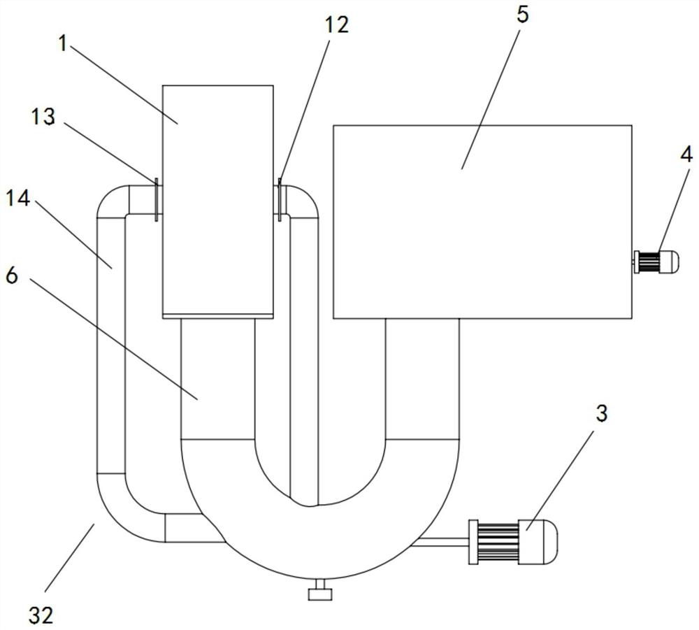
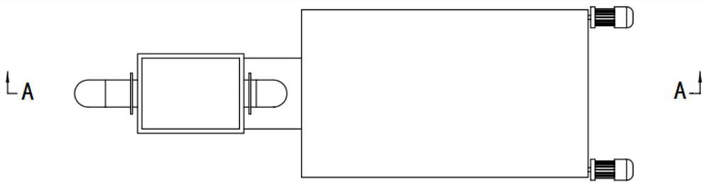
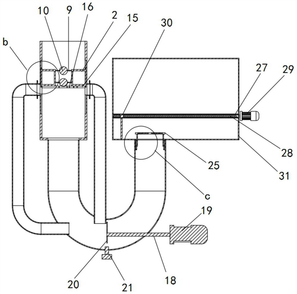
[0025] The object of the present invention is to provide a groundwater decompression drainage device to solve the above-mentioned problems in the prior art, and to be able to control the groundwater drainage pressure.

[0026] In order to make the above objects, features and advantages of the present invention more comprehensible, the present invention will be further described in detail below in conjunction with the accompanying drawings and specific embodimen...


PUM


Abstract

The invention discloses an underground water pressure reduction drainage device, and relates to the field of urban underground water drainage equipment. The underground water pressure reduction drainage device comprises a drainage pipe, a pressure relief plate, a pressure relief pipe and a water collection tank, wherein the drainage pipe comprises a water inlet end and a water outlet end, the water outlet end is used for communicating with the water collection tank, at least one drainage hole is formed in the pressure relief plate, the pressure relief plate is movably arranged in the drainage pipe, a pressure relief pipe connector is formed in the side wall of the drainage pipe, one end of the pressure relief pipe is used for communicating with the pressure relief pipe connector, the other end of the pressure relief pipe is used for communicating with the water collection tank, when the water pressure of the water inlet end is not larger than first water pressure, the upper edge, opposite to the pressure relief pipe connector, of the pressure relief plate is not lower than the highest point of the pressure relief pipe connector, and when thewater pressure of the water inlet end is larger than the first water pressure, the pressure relief plate can move downwards along the drainage pipe under the pressure effect of water, so that the upper edge, opposite to the pressure relief pipe connector, of the pressure relief plate is lower than the highest point of the pressure relief pipe connector. The underground water pressure reduction drainage device can control underground water drainage pressure.

Description

technical field [0001] The invention relates to the field of urban groundwater discharge equipment, in particular to a groundwater decompression drainage device. Background technique [0002] In recent years, with the development of cities, people pay more and more attention to underground drainage facilities. At present, some underground structures in cities have no balance between upper load and buoyancy. When there is a lot of rain, the rise of groundwater level will affect the anti-floating structure of buildings. The existing anti-floating methods include passive anti-floating methods and active anti-floating methods. The passive anti-floating method has high cost and long construction time, which is difficult to meet people's requirements; while the existing active anti-floating method has low cost, but it does not Without groundwater pressure control, the groundwater drainage pressure cannot be controlled within a limited range, which will easily lead to excessive dra...

Claims


Application Information

Patent Timeline
IPC IPC(8): E02D19/06E02D19/20
CPCE02D19/06E02D19/20
Inventor 杨彦利孙玉壮王金喜孙利辉
Owner HEBEI UNIV OF ENG
Why Eureka
Try Eureka