
Rock slice amplifying and imaging device, system and method

A technology of imaging device and generating device, which is applied in the direction of using radiation for material analysis, etc., can solve the problems of insufficient display of pore structure characteristics, inability to apply, and low magnification of CT scan results.

Pending Publication Date: 2021-08-31
PETROCHINA CO LTD
View PDF6 Cites 0 Cited by
  • Summary
  • Abstract
  • Description
  • Claims
  • Application Information

AI Technical Summary

Problems solved by technology

However, due to the relatively small size of the core model, the magnification of the CT scan results is not strong enough to show the characteristics of the pore structure
However, nano-CT technology is affected by the fact that the sample is only at the micron scale, so it cannot be applied in core-level experiments.

Method used


Image

  • Rock slice amplifying and imaging device, system and method
  • Rock slice amplifying and imaging device, system and method
  • Rock slice amplifying and imaging device, system and method

Examples


Embodiment Construction

[0082] In order to enable those skilled in the art to better understand the technical solutions in this specification, the technical solutions in the embodiments of the application will be clearly and completely described below in conjunction with the drawings in the embodiments of the application. Obviously, the described The embodiments are only some of the embodiments of the present application, but not all of them. Based on the embodiments in this application, all other embodiments obtained by persons of ordinary skill in the art without making creative efforts belong to the scope of protection of this application.

[0083] The inventors found that the development and research of the prior art are as follows:

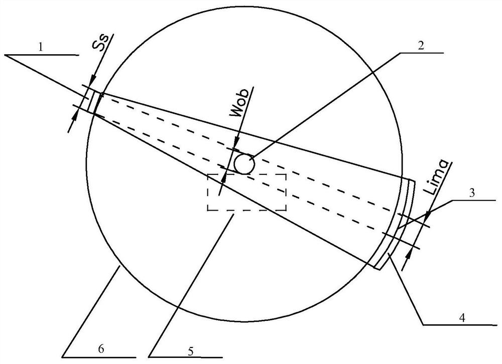
[0084] In the field of rock structure analysis, using the characteristics of X-ray penetration, there are usually two methods of rock structure scanning: conventional and microscopic, see Figure 1(a) and Figure 1(b). Fig. 1 (a) is the structure of a large-scale med...


PUM


Abstract

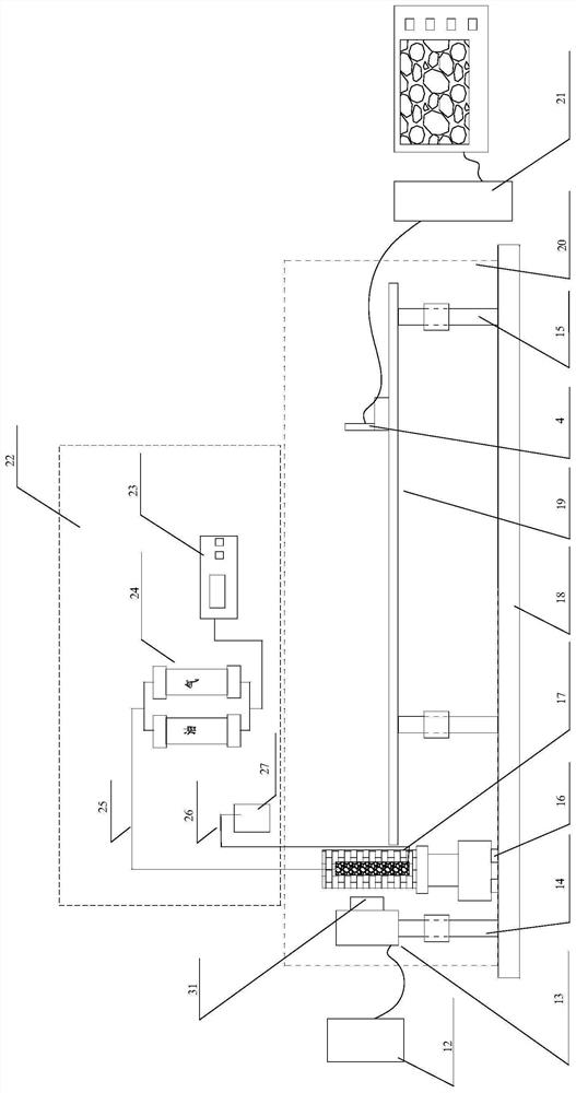
The invention provides a rock slice amplifying and imaging device, system and method. The device comprises a cover body which is used for preventing X-rays from leaking, and a rock slice sample containing device, an X-ray receiving plate and an X-ray generation device which are separately arranged in the cover body, so that the X-rays with scattering angles and emitted by the X-ray generation device penetrate through a target rock slice sample in the rock slice sample containing device. The X-ray generating device, the rock slice sample containing device and the X-ray receiving plate are sequentially arranged along the length direction of the cover body; the X-ray receiving plate is used for moving along the length direction and / or the width direction of the cover body in an area between the rock slice sample containing device and the inner wall of one side of the cover body so as to amplify and image the target rock slice sample through which X-rays penetrate. According to the invention, the amplification and imaging effect of a rock slice can be improved, and the definition of a rock pore structure and internal fluid recognition can be improved.

Description

technical field [0001] The present application relates to the technical field of oilfield development, and in particular to a rock thin section magnification imaging device, system and method. Background technique [0002] With the gradual deepening of the oil displacement mechanism, more and more attention has been paid to understanding the characteristics of fluid migration in pores, and visual observation is the most direct method for understanding. However, the scale of pores and channels is usually in the range of 0.1 μm to 1 mm, and direct observation is limited by various conditions. How to establish a zoom-in observation method and break through the limitations of conditions is a problem that needs to be overcome. [0003] The observation method of fluid flow in the pore structure usually adopts optical visualization method. Use the reflected light to observe the flow state on the surface of the oil displacement model, use the transmitted light to observe the fluid ...

Claims


Application Information

Patent Timeline
IPC IPC(8): G01N23/04
CPCG01N23/04
Inventor 陈兴隆鞠斌山刘楠楠郭金川贾宁洪
Owner PETROCHINA CO LTD
Learn More