Supercharge Your Innovation With Domain-Expert AI Agents!

Method and apparatus for controlling electric power flow in a battery system

一种电池系统、电功率的技术,应用在控制系统、电池断开电路、电池电路装置等方向,能够解决增加内部电池阻抗、锂析出电池影响、不受控制循环电流等问题

Pending Publication Date: 2021-08-31
GM GLOBAL TECH OPERATIONS LLC
View PDF11 Cites 0 Cited by
  • Summary
  • Abstract
  • Description
  • Claims
  • Application Information

AI Technical Summary

Problems solved by technology

Additionally, in cold weather conditions, high discharge loads may drive different amounts of polarization between the battery packs in the battery system, which can lead to uncontrolled circulating currents once the load is removed, and can lead to Lithium leaching and other effects in batteries
Lithium precipitation in the battery can increase the internal battery impedance and reduce the battery charging capacity, thereby affecting the service life of the battery pack

Method used

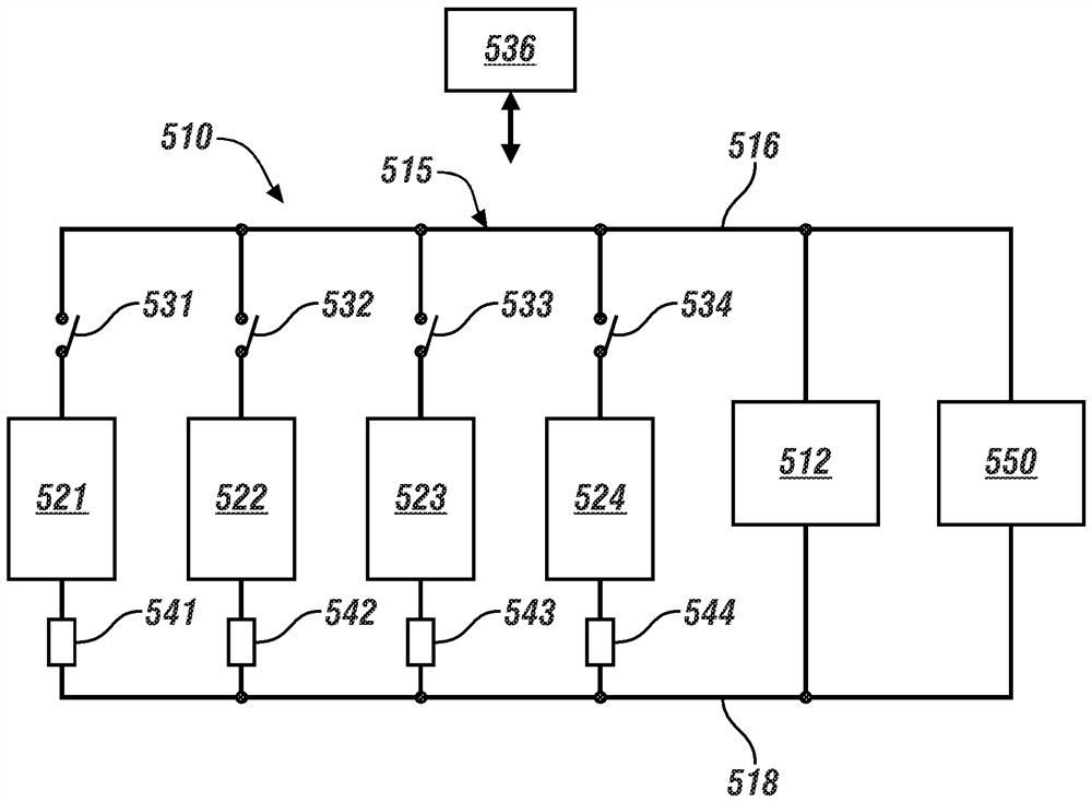
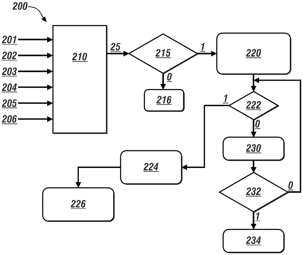
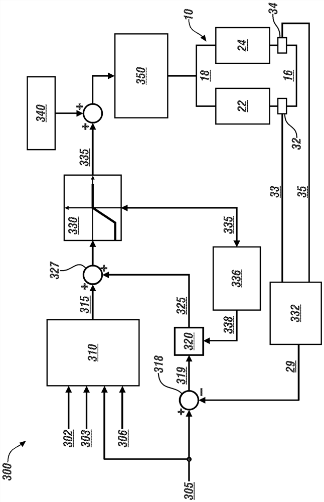

Image

  • Method and apparatus for controlling electric power flow in a battery system
  • Method and apparatus for controlling electric power flow in a battery system
  • Method and apparatus for controlling electric power flow in a battery system

Examples


Embodiment Construction

[0084] As described and illustrated herein, the components of the disclosed embodiments may be arranged and designed in a variety of different configurations. Accordingly, the following detailed description is not intended to limit the scope of the disclosure as claimed, but is merely representative of possible embodiments thereof. Additionally, although numerous specific details are set forth in the following description in order to provide a thorough understanding of the embodiments disclosed herein, certain embodiments can be practiced without some of these details. Also, for the purpose of clarity, certain technical material that is understood in the related technical fields has not been described in detail to avoid unnecessarily obscuring the present disclosure. Furthermore, the drawings are in simplified form and are not to exact scale. Directional terms such as top, bottom, left, right, upper, above, above, below, below, rear and front may be used with respect to the d...


PUM


Abstract

The invention relates to a method and an apparatus for controlling an electrical power flow in a battery system. The battery system is electrically connected to a power bus that is arranged to supply electric power to an on-vehicle actuator such as an electric traction machine. Controlling electric power flow in the battery pack includes determining states of charge for the plurality of battery packs, identifying one of the battery packs as a weakest battery pack based upon the states of charge, and determining an internal circulating current being transferred via the wiring harness that is associated with charging of the weakest battery pack. Electric power transfer through the wiring harness and the power bus is controlled such that the internal circulating current is less than an internal circulating current limit. In one embodiment, the internal circulating current limit is determined in relation to battery temperature.

Description

Background technique [0001] Vehicles and other systems employ DC power sources in the form of rechargeable battery packs to supply electrical power for vehicle propulsion and to provide other functions. A battery system may include multiple battery packs arranged in parallel and / or in series. [0002] An imbalance may exist between the states of charge of the battery packs employed in the battery system, where one of the battery packs has a higher state of charge than another of the battery packs. Imbalances between states of charge of battery packs employed in battery systems can be unavoidable due to current flow characteristics linked to battery voltage potential, charging schemes, especially so-called fast charging schemes, differential aging of battery packs, Variations due to temperature in the battery pack and errors in estimating the state of charge. [0003] The difference in state of charge may result in internal circulating currents in which one battery pack with ...

Claims


Application Information

Patent Timeline
Patent Type & Authority Applications(China)
IPC IPC(8): H02J7/00H02P27/06H01M10/42B60L58/18B60L3/00
CPCH02J7/0016H02P27/06B60L58/18B60L3/0046H01M10/4207H02J2207/30B60L58/14B60L58/22B60L2240/545Y02T10/70Y02E60/10H02J7/0063H02J7/007192H02J7/0013H02J7/00306H02J2310/48H02J7/14B60L58/21H02J7/00304H02J7/0031G01R31/382H02J7/00309
Inventor 王跃云A·V·米图塔G·M·西曼J·班内尔
Owner GM GLOBAL TECH OPERATIONS LLC
Features
  • R&D
  • Intellectual Property
  • Life Sciences
  • Materials
  • Tech Scout
  • Unparalleled Data Quality
  • Higher Quality Content
  • 60% Fewer Hallucinations
Learn More