Hand-operated stamp having a tilting element

A technology of seals and components, applied in the field of two locking elements, can solve problems such as complex structures and large manufacturing costs

Active Publication Date: 2021-08-31
刻乐圃印章制造斯高贝有限两合公司
View PDF9 Cites 0 Cited by
  • Summary
  • Abstract
  • Description
  • Claims
  • Application Information

AI Technical Summary

Problems solved by technology

Such a locking mechanism is associated with consider

Method used


Image

  • Hand-operated stamp having a tilting element
  • Hand-operated stamp having a tilting element
  • Hand-operated stamp having a tilting element

Examples


Embodiment Construction

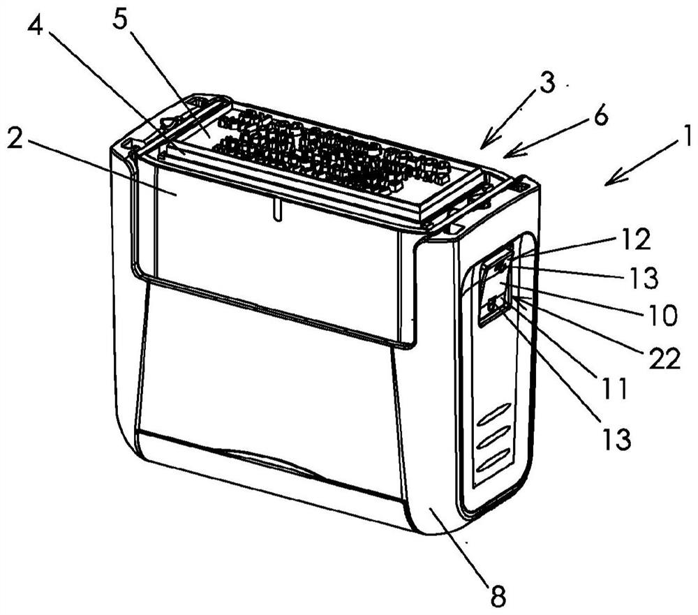
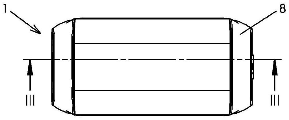
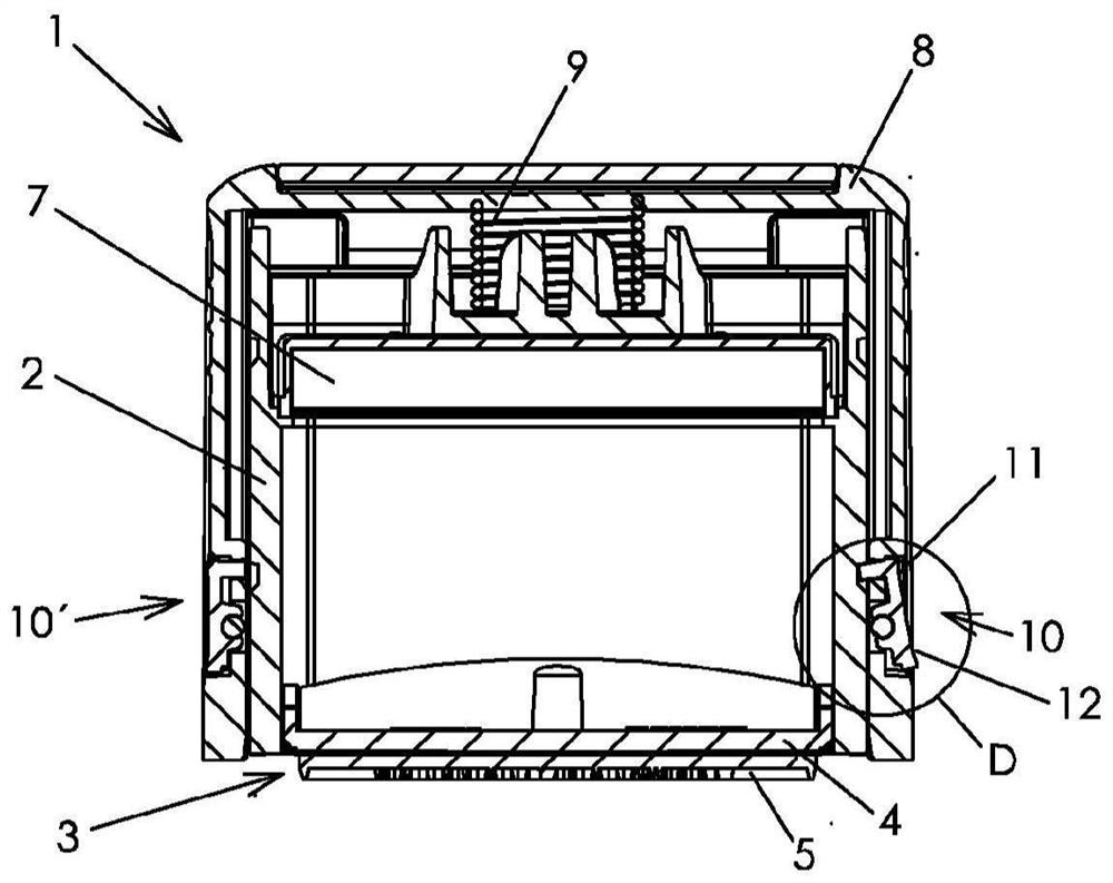
[0036] figure 1 A manual stamp 1 , which is designed as a self-inking stamp with upper impact inking, is shown partially from below, ie towards the underside or stamping side. image 3 along figure 2 The sectional view shown in section line III-III shows the same manual stamp 1 . The manual stamp 1 has a housing 2 , in which a stamp unit 3 is mounted, which has a stamp plate 5 mounted on a plate carrier 4 . As an alternative or supplement to the stamp plate 5, a font set (not shown) can also be provided. in accordance with figure 1 with 3 In the example of , the stamp plate 5 is arranged in the stamping opening 6 at the bottom end of the housing 2 , ie the manual stamp 1 is displayed in a space-saving delivery position. In the imprinting position, the stamp plate 5 is not completely exposed, unlike in the delivery position; instead, the relief or printing relief of the stamp plate 5 lies in a plane with the underside of the housing 2, i.e. on the surface of the object to...


PUM


Abstract

The invention relates to a hand-operated stamp (1), comprising a housing (2), in which a stamp unit (3) is mounted, which is coupled to an actuating part (8), which can be slid relative to the housing (2), wherein: the actuating part (8) has a locking element (10, 10') for limiting the sliding of the actuating part (8) relative to the housing (2); and the locking element (10, 10') is designed as a tilting element (10a) on a tilt shaft (14). The invention further relates to a method for releasing a blocking position of a hand-operated stamp (1), wherein: the actuating part (8) has a cut-out (22) for receiving the tilting element (10a); the tilt shaft (14) is arranged in the cut-out (22); the actuating part (8) has a supporting strut (23) in the cut-out (22); and the supporting strut (23) is arranged parallel to the tilt shaft (14).

Description

technical field [0001] The invention relates to a manual stamp having a housing in which a stamp unit coupled to an operating member movable relative to the housing is supported, the operating member has a function for limiting the movement of the operating member relative to the housing The locking element is configured as a pivot element on a pivot shaft, the operating part has a recess for accommodating the pivot element, and the pivot shaft is arranged in this recess. The invention also relates to a method for releasing the locked position of a manual stamp having a housing in which a stamp unit coupled to an operating part movable relative to the housing is supported, the operating part having a locking The locking element limits the movement of the operating part relative to the housing in the locking position. [0002] Restricting the movement of the operating part relative to the housing can be achieved, for example, by locking or fixing the operating part on the hous...

Claims


Application Information

Patent Timeline
IPC IPC(8): B41K1/40B41K1/42
CPCB41K1/02B41K1/36B41K1/40B41K1/50B41K1/42
Inventor J·威尔弗林格斯代尔
Owner 刻乐圃印章制造斯高贝有限两合公司
Why Eureka
Try Eureka