
Battery module and battery module manufacturing method

A technology for battery modules and manufacturing methods, which is applied to secondary batteries, final product manufacturing, battery pack components, etc., and can solve problems such as pressurization deviations

Pending Publication Date: 2021-09-03
TOYOTA JIDOSHA KK
View PDF10 Cites 0 Cited by
  • Summary
  • Abstract
  • Description
  • Claims
  • Application Information

AI Technical Summary

Problems solved by technology

[0004] However, in Patent Document 1, since the battery pack is given a constraining load (pressurization force) by pressing the battery pack into the storage portion of a storage case such as a module case as described above, if the battery pack is damaged due to manufacturing errors, If there is a deviation in the size, there is a possibility of deviation in the pressurization force

Method used


Image

  • Battery module and battery module manufacturing method
  • Battery module and battery module manufacturing method
  • Battery module and battery module manufacturing method

Examples


Embodiment Construction

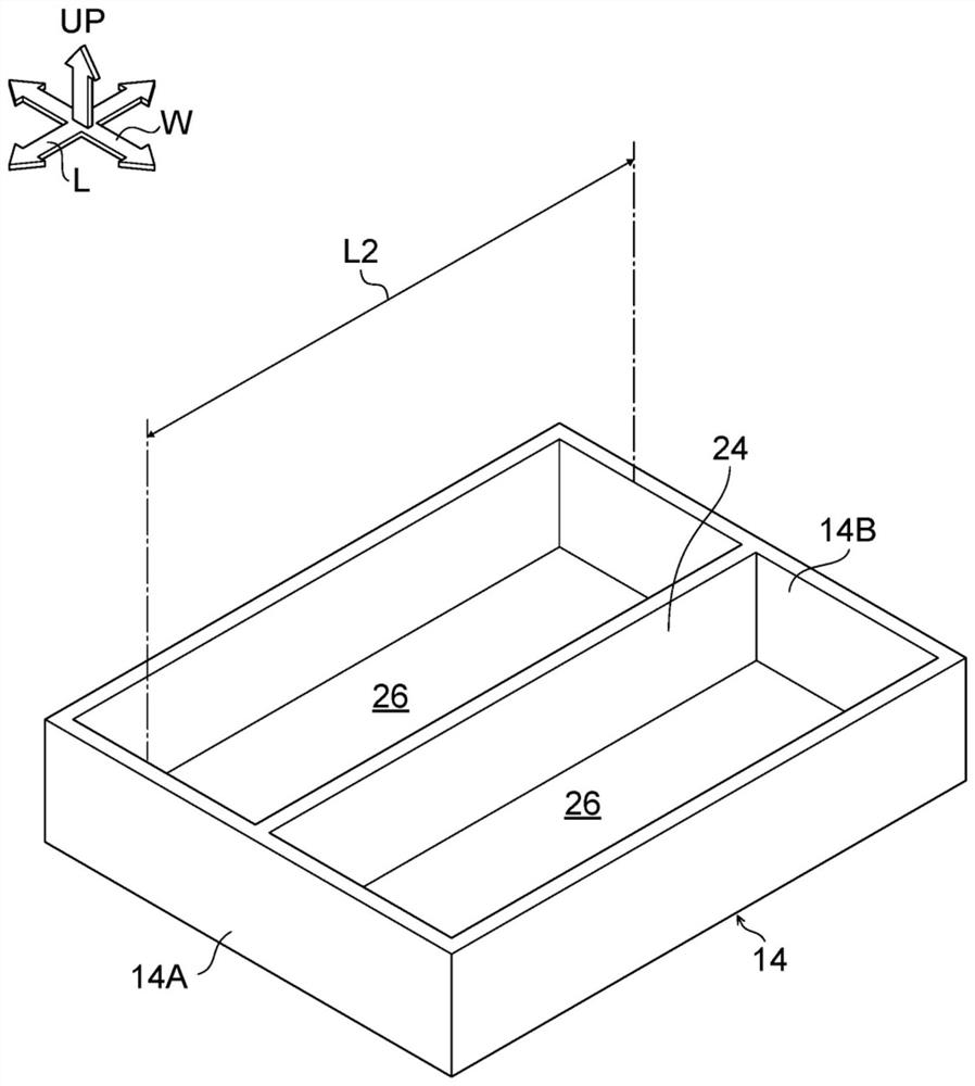
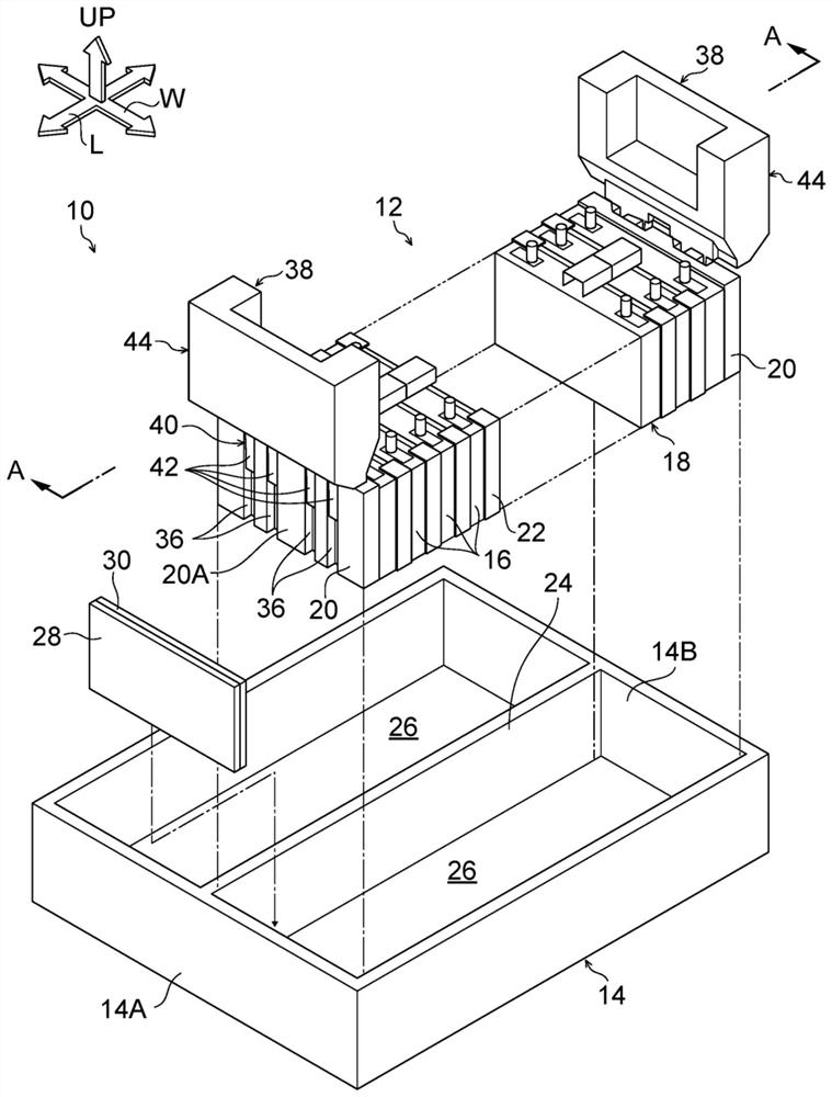
[0052] The battery module 10 according to the embodiment of the present disclosure will be described with reference to the drawings. In addition, arrow UP, arrow L, and arrow W shown appropriately in each figure indicate the upward direction, the longitudinal direction, and the width direction of the battery module 10 according to the present embodiment, respectively.

[0053]

[0054] First, the structure of the battery module 10 according to the embodiment of the present disclosure will be described.

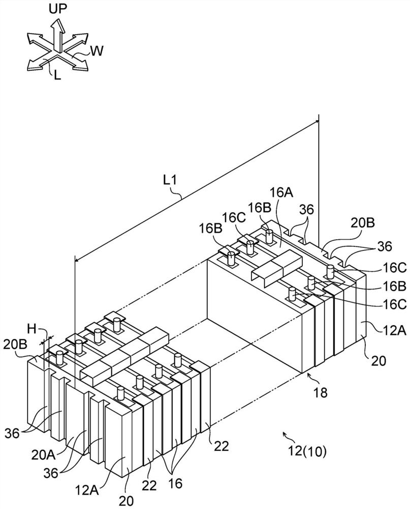
[0055] figure 1 A perspective view of the battery pack 12 constituting a part of the battery module 10 viewed from an obliquely upper side is shown in .

[0056] like figure 1 As shown, the battery pack 12 is configured to include a battery stack 18 in which a plurality of single cells 16 are stacked in the horizontal direction. In addition, in the battery pack 12 , end plates 20 made of resin are respectively provided at both ends of the battery stack 18 along the stacki...


PUM


Abstract

The present invention relates to a battery module and a method for manufacturing the battery module, the battery module comprising: a box-shaped housing case, the upper side of which is opened; a battery pack in which a plurality of unit cells are stacked in the horizontal direction and which is housed in the housing case; and a plurality of types of interstitial pieces made of different materials and disposed between the battery pack and the housing case in a state in which the battery pack is pressurized in the stacking direction of the single cells.

Description

technical field [0001] The present disclosure relates to a battery module and a method of manufacturing the battery module. Background technique [0002] Japanese Unexamined Patent Application Publication No. 2018-032519 (Patent Document 1) discloses a technology in which a battery module is provided with: a box-shaped module case with an upper portion opened; and a battery pack housed in the module. In the housing, the battery pack-side opposing surface and the housing-side opposing surface that face each other between the battery pack and the module housing are each inclined at approximately the same angle. [0003] Therefore, in Patent Document 1, the restraint load can be applied to the battery pack by pressing the battery pack into the housing portion of the module case. [0004] However, in Patent Document 1, since the battery pack is given a constraining load (pressurization force) by pressing the battery pack into the storage portion of a storage case such as a modu...

Claims


Application Information

Patent Timeline
IPC IPC(8): H01M50/264H01M50/209H01M50/244
CPCH01M10/0481H01M50/209H01M50/244Y02P70/50Y02E60/10H01M50/291H01M50/293H01M50/289
Inventor 山崎信之
Owner TOYOTA JIDOSHA KK
Learn More