Cable lap joint device

A technology of laps and cables, which is applied to the equipment, circuit, connection, etc. of connecting/terminating cables. It can solve the problems of water leakage at the terminals, misalignment of the cable cores at the terminals, and potential safety hazards, and achieve a waterproof safety factor. , the effect of improving the safety factor

Inactive Publication Date: 2021-09-03
刘木林
View PDF0 Cites 0 Cited by
  • Summary
  • Abstract
  • Description
  • Claims
  • Application Information

AI Technical Summary

Problems solved by technology

[0002] The cable is made of one or more mutually insulated conductors and the entire outer surface is covered with a highly insulating covering layer. It is a wire that transmits power or information from one place to another. After the cable is laid, in order to make it a For a continuous line, each section of the line must be connected as a whole. At this time, it is necessary to overlap the segmented cables so that the cables of each section are connected to each other to form a whole. The cable overlapping method is usually manual, while the traditional If the lap joint is too loose, it is easy to leak water and electricity, and there is a safety hazard. If the joint is too tight, the direct lap joint of the cable core will be misplaced due to the pressure of a large external force.

Method used


Image

  • Cable lap joint device
  • Cable lap joint device
  • Cable lap joint device

Examples


Embodiment 1

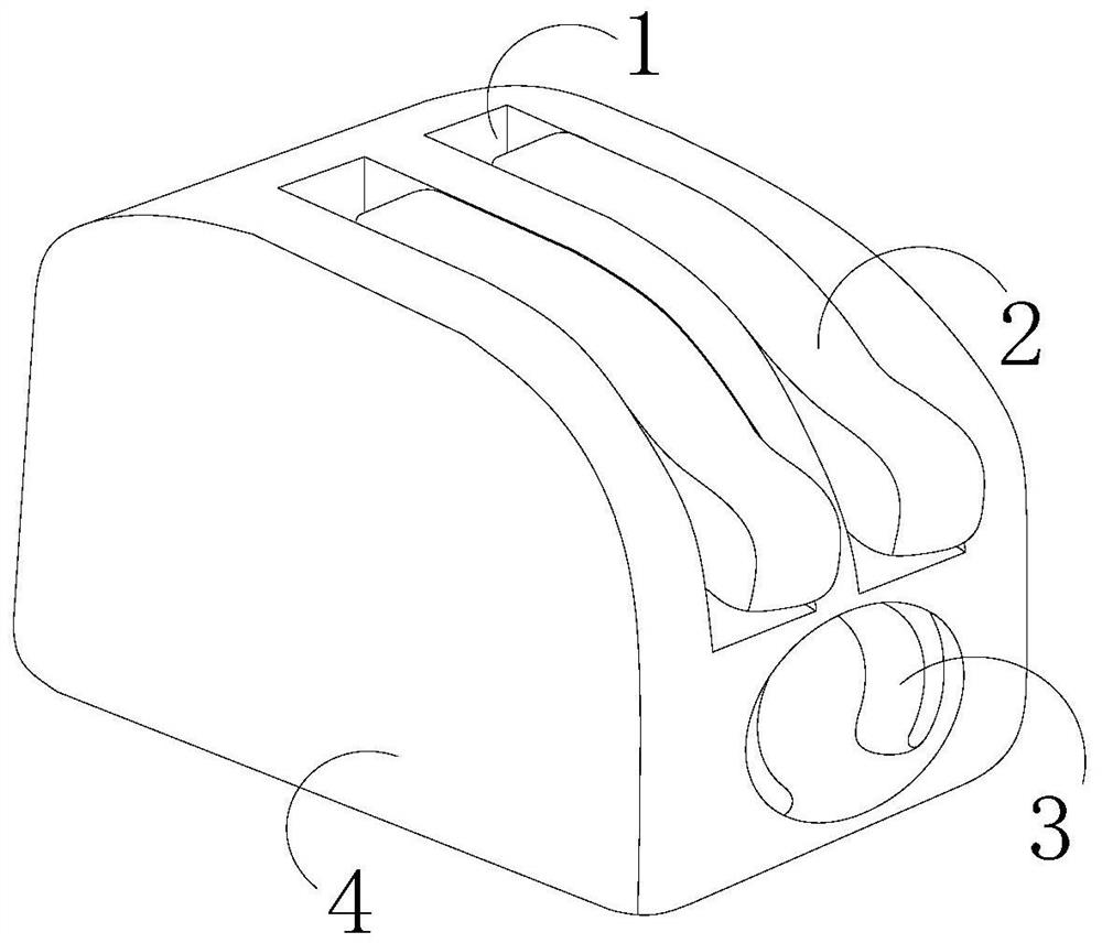
[0025] see Figure 1-Figure 5 , the present invention provides a cable splicer, the structure of which includes a fixing groove 1, a driving device 2, an overlapping end 3, and a housing 4, the fixing groove 1 is installed on the top of the housing 4, and the fixing groove 1 is embedded with The form is installed on the housing 4, the housing 4 is provided with an overlapping end 3, the overlapping end 3 penetrates the housing 4, the driving device 2 is connected with the overlapping end 3, the driving The device 2 is installed on the fixing groove 1 .

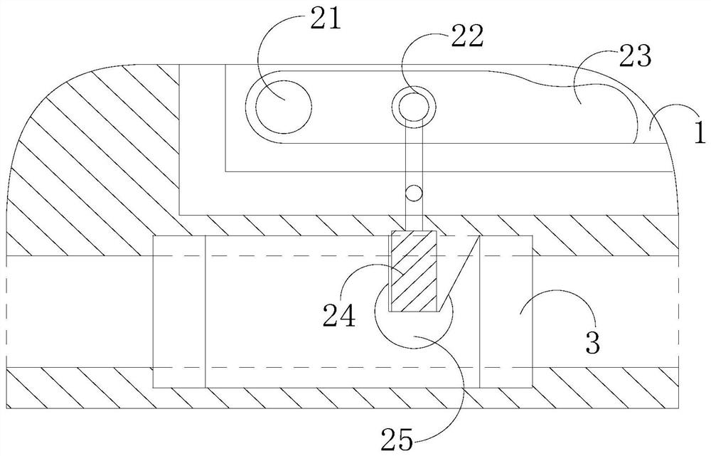
[0026] The driving device 2 is composed of a positioning shaft 21, a trailing end 22, a handle 23, an electric energy block 24, and a energization groove 25. The positioning shaft 21 runs through one end of the handle 23 and the handle 23 is installed in the fixing groove 1. The handle 23 is provided with a traction end 22, the traction end 22 is connected with the electric energy block 24, and the electric energy block 24 is...


PUM


Abstract

The invention discloses a cable lap joint device, and the lap joint device structurally comprises a fixing groove, a driving device, a lap joint end and a shell; the fixing groove is formed in the top of the shell, the fixing groove is formed in the shell in an embedded mode, the lap joint end is arranged on the shell and penetrates through the shell, the driving device is connected with the lap joint end, and the driving device is installed on the fixing groove. The invention has the beneficial effects that the separation and embedding states of the electric energy block and the electrifying groove are alternately changed by controlling the pull-up and pressing-down of the handle, so that the heating block obtains electric energy for heating to generate hot air which acts on the waterproof film, and the waterproof film is heated to shrink and is attached to the exposed position of the cable, so that the cable is protected, waterproof is effectively achieved, and the safety coefficient of cable lap joint is improved.

Description

technical field [0001] The invention relates to the field of cables, in particular to a cable lapping device. Background technique [0002] The cable is made of one or more mutually insulated conductors and the entire outer surface is covered with a highly insulating covering layer. It is a wire that transmits power or information from one place to another. After the cable is laid, in order to make it a For a continuous line, each section of the line must be connected as a whole. At this time, it is necessary to overlap the segmented cables so that the cables of each section are connected to each other to form a whole. The cable overlapping method is usually manual, while traditional If the lap joint method is too loose, it is easy to leak water and electricity, and there are safety hazards. If the joint end is too tight, it is easy to cause the direct lap joint of the cable core to be dislocated due to the pressure of a large external force. Contents of the invention [...

Claims


Application Information

Patent Timeline
IPC IPC(8): H01R13/52H01R13/629H01R13/639H02G1/14
CPCH01R13/629H01R13/639H01R13/52H02G1/14
Inventor 刘木林
Owner 刘木林
Why Eureka
Try Eureka