
Local railway dispatching station monitoring platform

A monitoring platform and railway technology, applied in the field of data transmission, can solve the problems of high maintenance costs, huge waste, and inability to play, and achieve the effects of reducing capital investment, flexibly arranging traffic flow, and improving labor efficiency and operation safety.

Pending Publication Date: 2021-09-03
韩伟
View PDF7 Cites 0 Cited by
  • Summary
  • Abstract
  • Description
  • Claims
  • Application Information

AI Technical Summary

Problems solved by technology

However, in some local railways and special lines, due to the small scale of enterprises and insufficient funds for equipment investment, and because of the unfixed and unbalanced traffic flow, dispatching and commanding do not require as many services as in CTC. The use of CTC system requires too much investment, and the CTC function cannot be fully utilized. Come out, the waste is huge, and the later maintenance costs are higher

Method used


Image

  • Local railway dispatching station monitoring platform
  • Local railway dispatching station monitoring platform
  • Local railway dispatching station monitoring platform

Examples


Embodiment 1

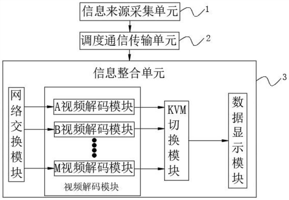
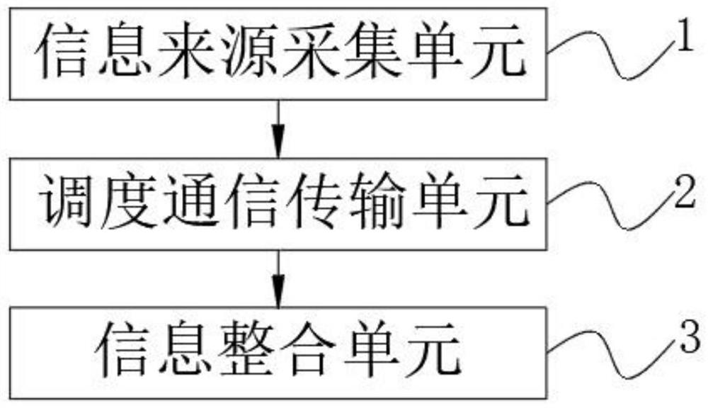
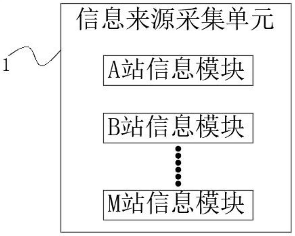
[0031] The present invention provides a monitoring platform for local railway dispatching stations, please refer to Figure 1-Figure 7 , including an information source collection unit 1, a dispatching communication transmission unit 2 and an information integration unit 3, the information source collection unit 1 is used to collect the usage conditions of a plurality of stations, and the dispatching communication transmission unit 2 is used to collect information on a plurality of railway stations The situation collected by the station is used for information transmission, and the information integration unit 3 is used to integrate and display the usage conditions of multiple railway station lines;

[0032] The information integration unit 3 includes a network switching module 31, a video decoding module 32, a KVM switching module 33 and a data display module 34. The network switching module 31 is used to receive the information transmitted by the scheduling communication tran...

Embodiment 2

[0042] When some dedicated lines do not have station communication transmission equipment, the video encoding module 12 and the video communication station communication transmission module 13 are connected by renting the broadband of the communication operator, so that the railway usage of the dedicated line is transmitted to the dispatching communication transmission unit 2, The dispatching communication transmission unit 2 transmits the use of the special line railway to the information integration unit 3 for display, so that the dispatcher can grasp the occupation and idleness of the special line railway in real time, and the situation of the line used by the train and shunting operation, which is convenient for dispatching Employees can flexibly arrange traffic flow, improve labor efficiency and work safety.


PUM


Abstract

The invention relates to the technical field of data transmission, in particular to a local railway dispatching station monitoring platform. The system comprises an information source acquisition unit, a scheduling communication transmission unit and an information integration unit; the information source acquisition unit is used for acquiring the use conditions of multiple station tracks, and the scheduling communication transmission unit is used for transmitting the acquired information of multiple stations. The information integration unit is used for integrating the graphs of the multiple stations and displaying the graphs in real time; the information integration unit comprises a network switching module, a video decoding module, a KVM switching module and a data display module, and the video decoding module comprises a video decoding module A, a video decoding module B,..., and a video decoding module M, and is used for decoding videos of compressed railway battlefield graphs of a plurality of railway stations. The invention mainly aims to solve the problems that the investment for local railway dispatching monitoring by adopting a CTC system is too large, the CTC function cannot be completely played, the waste is great, and the later maintenance cost is high.

Description

technical field [0001] The invention relates to the technical field of data transmission, in particular to a monitoring platform for local railway dispatching stations. Background technique [0002] At present, the railway dispatching command uses the CTC system to transmit the real-time information of the station. CTC is suitable for the national railway trunk line system because of its multiple functions and equipment and high cost. However, in some local railways and special lines, due to the small scale of enterprises and insufficient funds for equipment investment, and because of the unfixed and unbalanced traffic flow, dispatching and commanding do not require as many services as in CTC. The use of CTC system requires too much investment, and the CTC function cannot be fully utilized. If it comes out, it is a lot of waste, and the later maintenance cost is relatively high. Instead, it is enough to only monitor and observe the usage of the station track lines, so there...

Claims


Application Information

Patent Timeline
IPC IPC(8): H04N5/765H04N7/18H04N19/42
CPCH04N5/765H04N19/42H04N7/181
Inventor 韩伟
Owner 韩伟
Learn More