
Vibration sensor

A vibration sensor, spring sheet technology, applied in instruments, measuring devices, measuring ultrasonic/sonic/infrasonic waves, etc., can solve the problems of reducing frequency parameters, limiting sensor frequency parameters, etc., to achieve the effect of high sensitivity

Pending Publication Date: 2021-09-07
威海广达勘探仪器有限公司
View PDF7 Cites 0 Cited by
  • Summary
  • Abstract
  • Description
  • Claims
  • Application Information

AI Technical Summary

Problems solved by technology

[0003] The present invention is to solve the technical problem that the metal spring sheet of the existing vibration sensor limits the frequency parameter of the sensor, and provides a vibration sensor with a reduced frequency parameter

Method used


Image

  • Vibration sensor
  • Vibration sensor
  • Vibration sensor

Examples


Embodiment Construction

[0024] Referring to the accompanying drawings, the present invention will be further described in detail with specific embodiments.

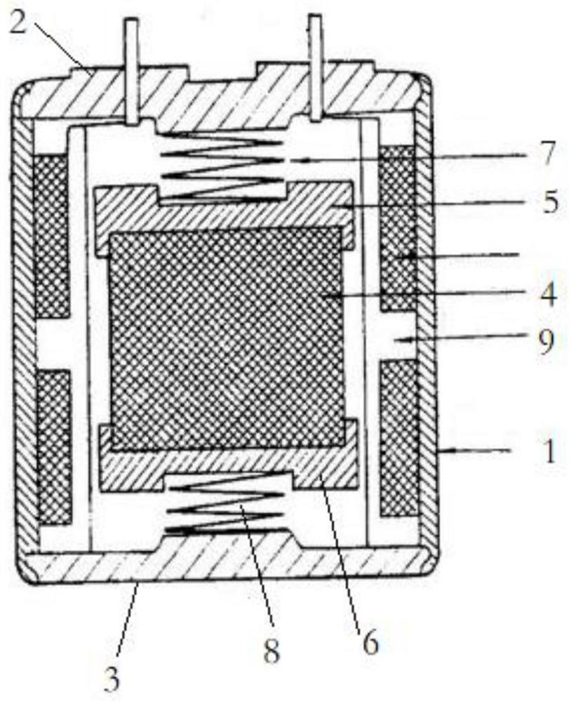
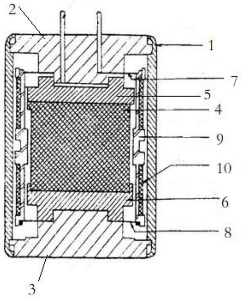
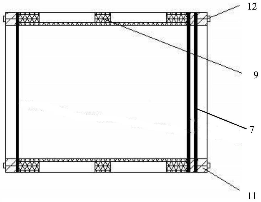
[0025] Such as Figure 1-2 As shown, the vibration sensor includes a housing 1, an upper cover 2, a lower cover 3, a magnetic steel 4, an upper magnetic shoe 5, a lower magnetic shoe 6, an upper spring piece 7, a lower spring piece 8, a coil holder 9, a coil 10, and an upper cover 2 is connected to the shell 1, the lower cover 3 is connected to the shell 1, the lower magnetic shoe 6 is connected to the lower cover 3, the magnetic steel 4 is connected to the lower magnetic shoe 6, the upper magnetic shoe 5 is connected to the magnetic steel 4, and the coil 10 is connected to the coil frame 9 connection, the coil frame 10 is set on the magnetic steel 4, the upper spring piece 7 is connected with the upper magnetic shoe 5, the lower spring piece 8 is connected with the lower magnetic shoe 6, the upper end of the coil frame 9 is connected with the p...


PUM


Abstract

The invention relates to a vibration sensor, which solves the technical problem that a metal spring piece of an existing vibration sensor limits frequency parameters of the sensor, and comprises a shell, an upper cover, a lower cover, magnetic steel, an upper magnetic boot, a lower magnetic boot, an upper spring piece, a lower spring piece, a coil rack and a coil, wherein the upper cover is connected with the shell, the lower cover is connected with the shell, the lower magnetic boot is connected with the lower cover. The magnetic steel is connected with the lower magnetic boot, the upper magnetic boot is connected with the magnetic steel, the coil is connected with the coil rack, the coil rack is sleeved on the magnetic steel, the upper spring piece is connected with the upper magnetic shoe, the lower spring piece is connected with the lower magnetic boot, the upper end of the coil rack is connected with the periphery of the upper spring piece, the lower end of the coil rack is connected with the periphery of the lower spring piece, and the upper spring piece is made of non-metallic materials, and the lower spring piece is made of a non-metal material. The vibration sensor can be used in the fields of exploration, engineering geophysical prospecting, earthquake monitoring, equipment vibration detection, aviation, spaceflight and the like.

Description

technical field [0001] The present invention relates to the technical field of magnetoelectric vibration sensors, in particular to a vibration sensor. Background technique [0002] As a vibration detection or monitoring technology, the magnetoelectric vibration sensor is a passive, economical and long-term use method with better results. It is used in exploration, engineering geophysical prospecting, earthquake monitoring, equipment vibration detection, aviation, Aerospace and other fields have a wide range of applications. The reference patent number is 2014200401093, a utility model patent named "seismic detector". The spring piece, the lower magnetic shoe is connected to the inner side of the lower cover, the magnetic steel is connected to the lower magnetic shoe, the upper magnetic shoe is connected to the magnetic steel, the coil frame is connected with a coil, the coil frame is set on the magnetic steel, the upper spring piece is connected to the upper magnetic shoe ...

Claims


Application Information

Patent Timeline
Patent Type & Authority Applications(China)
IPC IPC(8): G01H11/02
CPCG01H11/02
Inventor 星学奎
Owner 威海广达勘探仪器有限公司
Learn More