
Backfeed coupled folded loop antenna and mobile terminal

A loop antenna, coupled technology, applied in the field of back-feed coupled folded loop antenna and mobile terminals, can solve the problems of difficult antenna debugging and narrow bandwidth

Active Publication Date: 2019-06-21
HUIZHOU TCL MOBILE COMM CO LTD
View PDF6 Cites 0 Cited by
  • Summary
  • Abstract
  • Description
  • Claims
  • Application Information

AI Technical Summary

Problems solved by technology

Usually, the mobile phone antenna adopts front feed, and uses a combination of planar inverted F antenna (PIFA), inverted F antenna (IFA), monopole antenna (monopole) and ground plate to use antenna resonance, and the bandwidth of resonance is narrow
At the same time, facing the environment and layout of the current mobile phone, it is difficult to debug the antenna

Method used


Image

  • Backfeed coupled folded loop antenna and mobile terminal
  • Backfeed coupled folded loop antenna and mobile terminal
  • Backfeed coupled folded loop antenna and mobile terminal

Examples


Embodiment Construction

[0019] The present invention will be described in further detail below in conjunction with the accompanying drawings and embodiments.

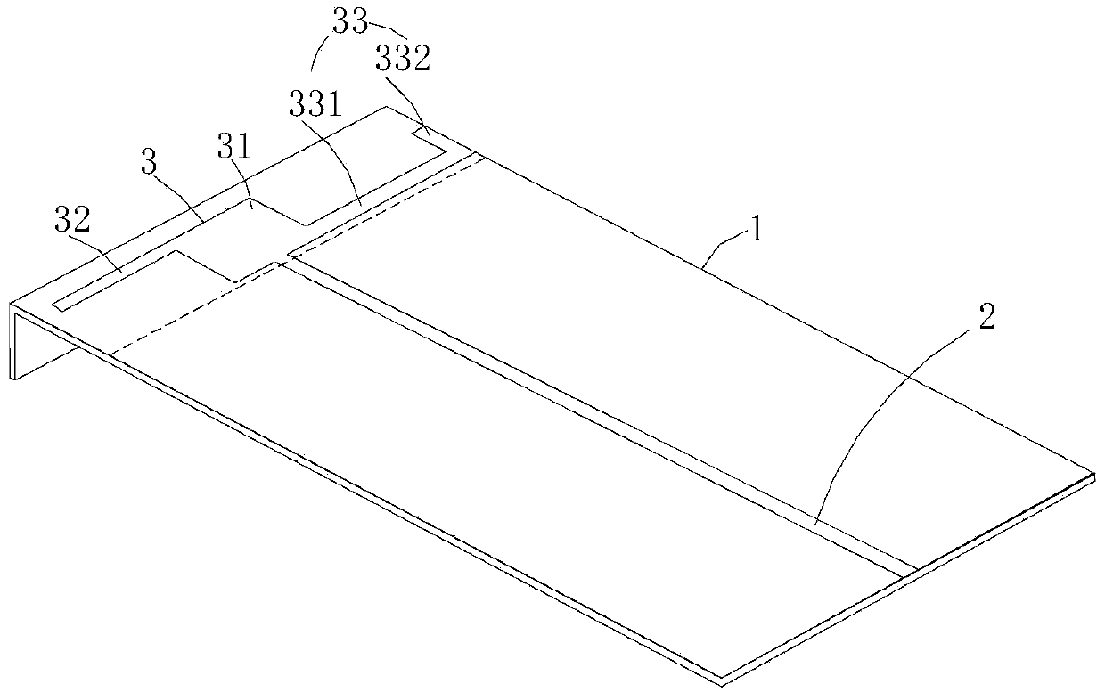
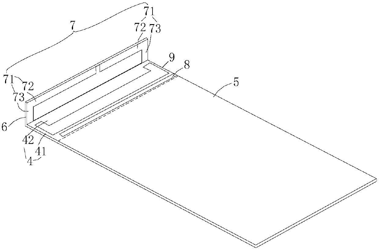
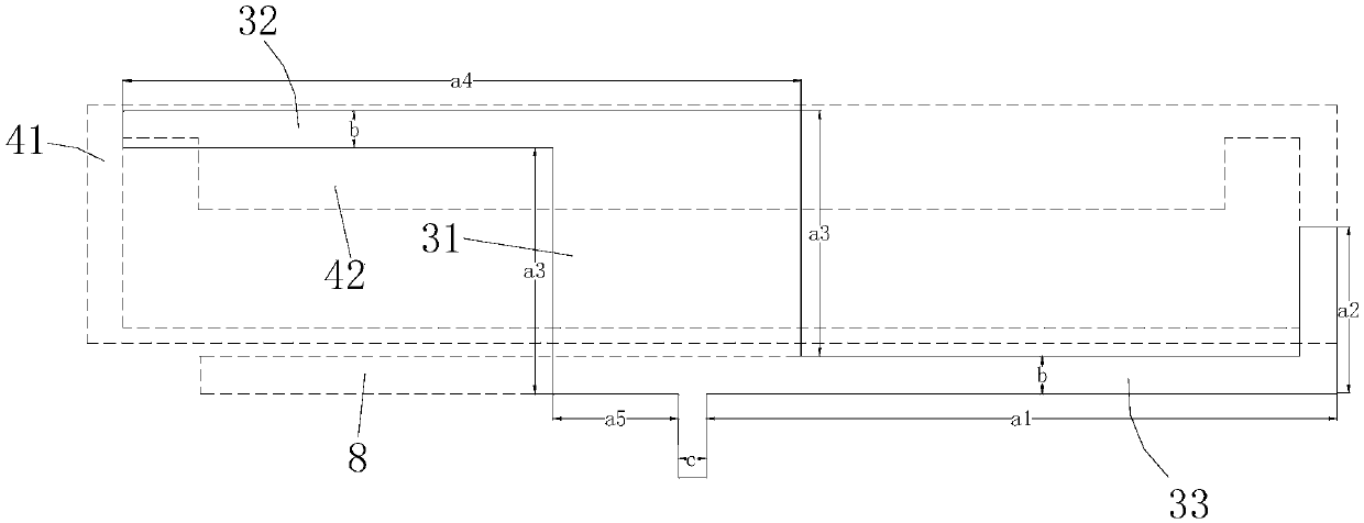
[0020] Such as figure 1 and figure 2 As shown, the back-feed coupled folded loop antenna of the present invention includes an antenna body disposed on a dielectric substrate 1, the dielectric substrate 1 is rectangular, and has a long side and a short side. 1 The microstrip line 2 on one side, the microstrip line 2 is a 50 ohm microstrip line, the microstrip line 2 extends from one short side of the dielectric substrate 1 to the other short side, between the dielectric substrate 1 and the microstrip line The vertical side (short side) of the strip line 2 is provided with a coupling feeder 3 near the edge, and a gap is arranged between the coupling feeder 3 and the long side and the short side of the dielectric substrate 1; the coupling feeder 3 It is the radiation part of the antenna, the coupling feeding part 3 is connected with the micros...


PUM


Abstract

The present invention provides a rear feed coupled folding loop antenna. The rear feed coupled folding loop antenna comprises an antenna body arranged on a dielectric substrate, the antenna body comprises a microstrip line arranged at one surface of the dielectric substrate, a coupled feeding portion is arranged at the edge close to one side, perpendicular to the microstrip line, of the dielectric substrate, the coupled feeding portion is connected with the microstrip line, the other surface of the dielectric substrate is provided with an earth plate, a loop antenna is arranged at the position, corresponding to the electrical portion position of the coupled feeding portion, on the earth plate, and the loop antenna is coupled with the coupled feeding portion; and the one side, adjacent to the loop antenna, of the dielectric substrate is provided with a bending portion, one surface, opposite to the loop antenna, on the bending portion is provided with a tuning branchknot, and a groove is arranged at the earth plate close to the loop antenna. The present invention further provides a mobile terminal. Compared to the prior art, the rear feed coupled folding loop antenna and the mobile terminal employ the coupled feeding portion as an antenna radiating body for high-frequency resonance, and employ a coupling mode for feeding of the loop antenna and the groove to realize low frequency so as to allow the antenna to cover low frequency and high frequency.

Description

technical field [0001] The invention relates to an antenna technology, in particular to a back-feed coupling folded loop antenna and a mobile terminal. Background technique [0002] At present, the frequency bands and standards of mobile phones in mobile terminals are increasing day by day, and the frequency bands used are becoming more and more extensive. With the development of next-generation mobile communication technologies such as 5G in the future, mobile phone antennas are increasingly becoming a difficult point in mobile phone hardware design. Usually, the mobile phone antenna adopts front-side feeding, and uses a combination of planar inverted-F antenna (PIFA), inverted-F antenna (IFA), monopole antenna (monopole) and grounding plate to use antenna resonance, and the bandwidth of resonance is narrow. At the same time, in the face of the environment and layout of the current mobile phone, it is difficult to debug the antenna. Contents of the invention [0003] In ...

Claims


Application Information

Patent Timeline
Patent Type & Authority Patents(China)
IPC IPC(8): H01Q1/38H01Q1/48H01Q1/50H01Q5/10H01Q5/20H01Q5/50H01Q7/02H01Q1/22H01Q1/24
CPCH01Q1/2258H01Q1/242H01Q1/38H01Q1/48H01Q1/50H01Q5/10H01Q5/20H01Q5/50H01Q7/02
Inventor 陈磊刘莉云
Owner HUIZHOU TCL MOBILE COMM CO LTD
Learn More