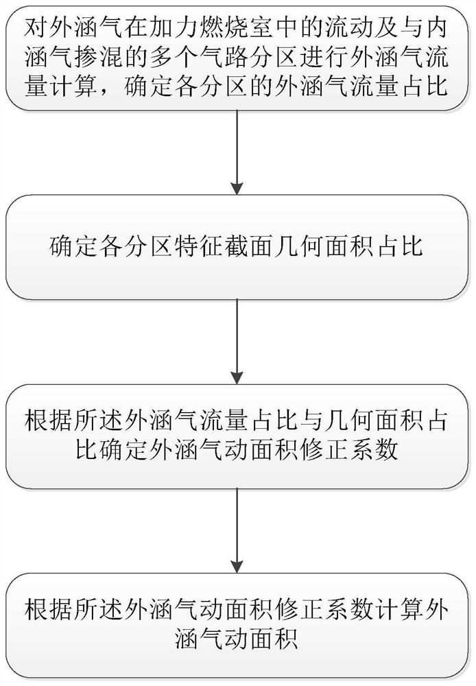
Method for determining pneumatic area of afterburner outer culvert with flow guide supporting plate
A technology for afterburner and determination method, which is applied in jet propulsion devices, machines/engines, special data processing applications, etc., and can solve problems such as inaccurate calculations and complicated calculation of afterburner aerodynamic area
- Summary
- Abstract
- Description
- Claims
- Application Information
AI Technical Summary
Problems solved by technology
Method used
Image

Examples
Embodiment Construction
[0034] In order to make the objectives, technical solutions and advantages of the implementation of the application clearer, the technical solutions in the implementation modes of the application will be described in more detail below with reference to the drawings in the implementation modes of the application. In the drawings, the same or similar reference numerals denote the same or similar elements or elements having the same or similar functions throughout. The described embodiments are some, but not all, embodiments of the present application. The embodiments described below by referring to the figures are exemplary and are intended to explain the present application, and should not be construed as limiting the present application. Based on the implementation manners in this application, all other implementation manners obtained by persons of ordinary skill in the art without creative efforts fall within the scope of protection of this application. Embodiments of the pr...
PUM
 Abstract
Description
Claims
Application Information