Motion error compensation algorithm based on unmanned aerial vehicle bistatic SAR system

A motion error, bistatic technology, used in radio wave measurement systems, radio wave reflection/re-radiation, utilization of re-radiation, etc., can solve problems such as high error degrees of freedom, difficulty in error parameters, and reduced error estimation accuracy.

Inactive Publication Date: 2021-07-30
BEIJING INSTITUTE OF TECHNOLOGYGY +1
View PDF2 Cites 2 Cited by
  • Summary
  • Abstract
  • Description
  • Claims
  • Application Information

AI Technical Summary

Problems solved by technology

However, under the bistatic condition, the spatial variability of the motion error of the small UAV system is greater than that of the traditional SAR system, and the motion errors in the range and azimuth directions are severely coupled, which greatly reduces the error estimation accuracy
Therefore, the traditional motion error compensation (MOCO, Motion Compensation) algorithm combined with space variation is no longer applicable
In addition, the transmitter and receiver are installed on different UAV platforms, each of which introduces motion errors, making the degrees of freedom (DOFs, Degrees of Freedom of motion error) of motion errors twice that of the single-station system, and the error parameters The estimation of is relatively difficult, and the problem of such a high degree of freedom of error has not been solved yet.

Method used


Image

  • Motion error compensation algorithm based on unmanned aerial vehicle bistatic SAR system
  • Motion error compensation algorithm based on unmanned aerial vehicle bistatic SAR system
  • Motion error compensation algorithm based on unmanned aerial vehicle bistatic SAR system

Examples


Embodiment Construction

[0038] Various exemplary embodiments, features, and aspects of the present disclosure will be described in detail below with reference to the accompanying drawings. While various aspects of the embodiments are shown in drawings, the drawings are not necessarily drawn to scale unless specifically indicated.

[0039] The word "exemplary" is used exclusively herein to mean "serving as an example, embodiment, or illustration." Any embodiment described herein as "exemplary" is not necessarily to be construed as superior or better than other embodiments.

[0040] In addition, in order to better illustrate the present disclosure, numerous specific details are given in the following specific implementation manners. It will be understood by those skilled in the art that the present disclosure may be practiced without some of the specific details. In some instances, methods and means well known to those skilled in the art are not described in detail in order to highlight the gist of t...


PUM


Abstract

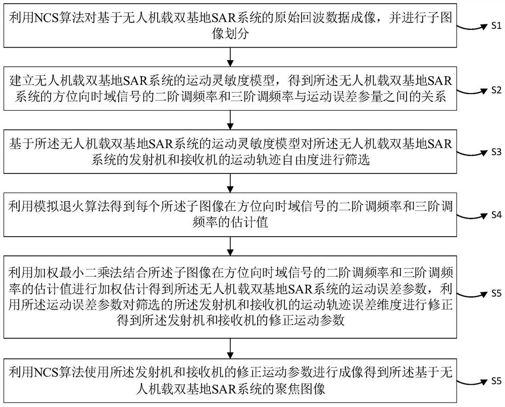
The invention provides a motion error compensation method based on an unmanned aerial vehicle-mounted bistatic SAR system. The difficulty of motion compensation is reduced by constructing a motion sensitivity model of a small unmanned aerial vehicle BiSAR system and reducing the degree of freedom of errors. Firstly, sub-image division is carried out on a coarse imaging result, meanwhile, a motion sensitivity model of a small unmanned aerial vehicle bistatic synthetic aperture radar system is established, the second-order frequency modulation rate and the third-order frequency modulation rate of azimuth time domain signals are expressed as the linear sum of several error degrees of freedom, and the error degree of freedom is screened by using the model. Then, error estimation values of the motion parameters are obtained through a simulated annealing algorithm and a weighted least square method, and finally, global motion compensation is achieved through the values. The motion compensation difficulty is reduced by reducing the degree of freedom of error, and global motion compensation is realized. The method is suitable for an imaging environment with relatively few sparse scene strong contrast areas, and the problem that a traditional motion error compensation algorithm is not applicable when the motion error of a transceiver has large space-variant characteristics in a small unmanned aerial vehicle BiSAR system is solved.

Description

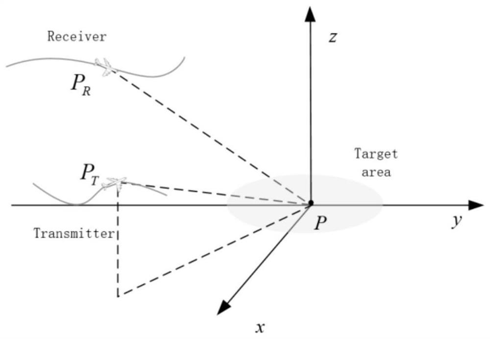
technical field [0001] The disclosure belongs to the technical field of bistatic synthetic aperture radar, and in particular relates to a motion error compensation algorithm based on a UAV-borne bistatic SAR system. Background technique [0002] Unmanned Aerial Vehicle Bistatic Synthetic Aperture Radar (UAV-BiSAR, Unmanned Aerial Vehicle Bistatic Synthetic Aperture Radar) is widely used in disaster search, land surveying and mapping, military monitoring and other fields because it can provide images that are not affected by weather conditions day and night. . However, under the bistatic condition, the spatial variability of the motion error of the small UAV system is greater than that of the traditional SAR system, and the motion errors in the range and azimuth directions are severely coupled, which greatly reduces the accuracy of error estimation. Therefore, the traditional motion error compensation (MOCO, Motion Compensation) algorithm combined with space variation is no ...

Claims


Application Information

Patent Timeline
Patent Type & Authority Applications(China)
IPC IPC(8): G01S13/90G01S7/40
CPCG01S13/9021G01S7/40
Inventor 刘飞峰曾涛王战泽高检何思敏
Owner BEIJING INSTITUTE OF TECHNOLOGYGY
Why Eureka
Try Eureka