Metal composite energy dissipater with double-order yield points for shock insulation layer

A technology of metal composite and yield point, which is applied in the direction of earthquake resistance, building components, building construction, etc., can solve the problems of unfavorable influence of structure, small initial yield force, high design, etc.

Pending Publication Date: 2021-09-10
BEIJING INST OF ARCHITECTURAL DESIGN
View PDF7 Cites 2 Cited by
  • Summary
  • Abstract
  • Description
  • Claims
  • Application Information

AI Technical Summary

Problems solved by technology

Therefore, the use of traditional metal dampers cannot match the large displacement characteristics of the seismic isolation layer of the seismic isolation building, and it cannot be applied to the large deformation position of the seismic isolation layer for energy dissipation and shock absorption design of the structure.
[0007] (2) Furthermore, the traditional metal damper usually has only one yield energy dissipation section, that is, the traditional metal damper can only power consumption
For example, if the traditional metal damper chooses to yield and consume energy at the stage of small earthquakes, its corresponding initial yield force will be small, and its energy dissipation and shock absorption effect will be poor under the action of medium and large earthquakes, and at the same time there will be fracture failure. danger; if the traditional metal damper choose...

Method used


Image

  • Metal composite energy dissipater with double-order yield points for shock insulation layer
  • Metal composite energy dissipater with double-order yield points for shock insulation layer
  • Metal composite energy dissipater with double-order yield points for shock insulation layer

Examples


Embodiment Construction

[0043] The technical solutions of the present invention will be clearly and completely described below with reference to the accompanying drawings. Obviously, the described embodiments are a part of the embodiments of the present invention, but not all of the embodiments. Based on the embodiments of the present invention, all other embodiments obtained by those of ordinary skill in the art without creative efforts shall fall within the protection scope of the present invention.

[0044] In the description of the present invention, it should be noted that the terms "center", "upper", "lower", "left", "right", "vertical", "horizontal", "inner", "outer", etc. The indicated orientation or positional relationship is based on the orientation or positional relationship shown in the accompanying drawings, which is only for the convenience of describing the present invention and simplifying the description, rather than indicating or implying that the indicated device or element must hav...


PUM


Abstract

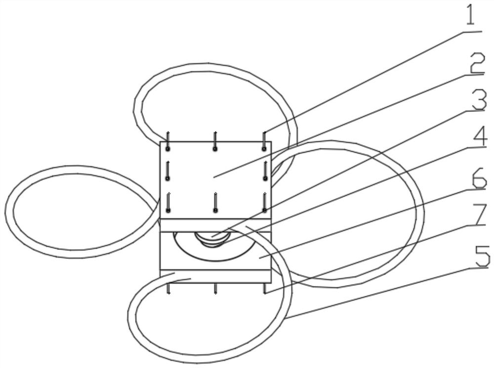
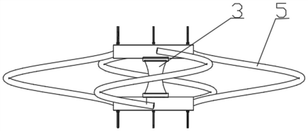
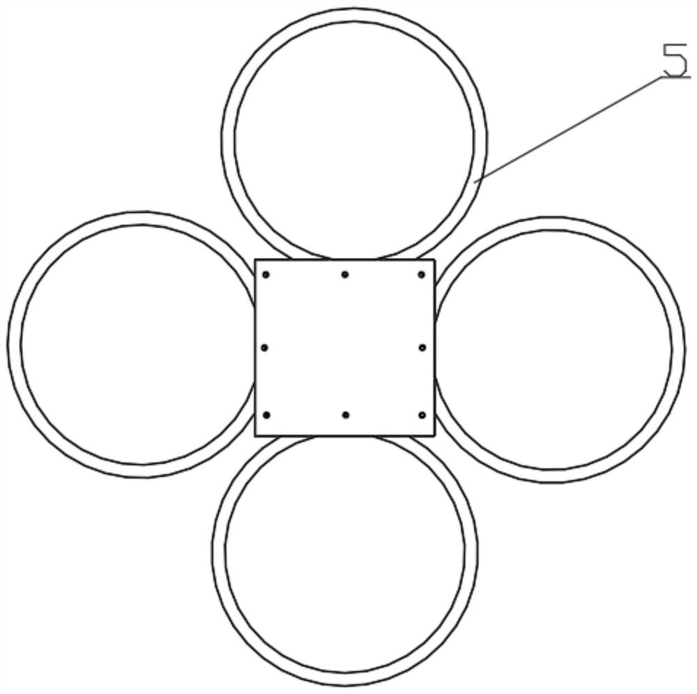
The invention provides a metal composite energy dissipater with double-order yield points for a shock insulation layer. The metal composite energy dissipater comprises a first yield energy dissipation section and a second yield energy dissipation section. The first yield energy dissipation section is formed by orthogonally arranging four groups of spiral steel bar energy dissipation units and is used for absorbing earthquake energy input in two directions; and the second yield energy dissipation section is made of a variable-cross-section yield energy dissipation lead pipe, and end plates are arranged at the upper end and the lower end of the second yield energy dissipation section to provide end restraint. The metal composite energy dissipater has the deformation capacity matched with large-earthquake displacement of the shock insulation layer, and under the action of a rare earthquake and under the condition that the shock insulation layer has larger displacement, the normal energy dissipation and shock absorption working state can still be kept; and meanwhile, the metal composite energy dissipater has the characteristic of double-order yield energy dissipation, the output of the metal energy dissipater can be increased in stages along with the increase of the earthquake action, a hysteretic energy dissipation curve of a damper is full under different earthquake magnitudes, and it is guaranteed that the metal composite energy dissipater has the excellent energy dissipation and shock absorption effect under the different earthquake magnitudes.

Description

technical field [0001] The invention relates to the technical field of building seismic isolation structures, in particular to a metal composite energy dissipator with double-order yield point for seismic isolation layers, which can also be referred to as a double-order yield point helical steel rod and Variable section lead pipe combination metal damper. Background technique [0002] Seismic isolation structure system refers to a structure system in which some kind of seismic isolation device is installed between the bottom of the upper structure of the building and the foundation surface to separate it from the foundation ground consolidated in the foundation. The seismic isolation layer of the seismic isolation system adopts seismic isolation bearings and other devices, and its horizontal rigidity is far lower than the lateral rigidity of the upper structure. Therefore, the natural vibration period of the structure is greatly extended, avoiding the excellent period of gro...

Claims


Application Information

Patent Timeline
IPC IPC(8): E04B1/98E04B1/36E04H9/02
CPCE04B1/98E04B1/36E04H9/021E04H9/0237
Inventor 朱忠义閤东东周忠发赵帆
Owner BEIJING INST OF ARCHITECTURAL DESIGN
Why Eureka
Try Eureka