Ejector for heat or work recovery system and heat or work recovery system

A recovery system, ejector technology, used in the field of heat recovery or work recovery systems

Pending Publication Date: 2021-09-10
CARRIER CORP
View PDF0 Cites 0 Cited by
  • Summary
  • Abstract
  • Description
  • Claims
  • Application Information

AI Technical Summary

Problems solved by technology

[0004] The purpose of the present invention is to solve o

Method used


Image

  • Ejector for heat or work recovery system and heat or work recovery system
  • Ejector for heat or work recovery system and heat or work recovery system
  • Ejector for heat or work recovery system and heat or work recovery system

Examples


Embodiment Construction

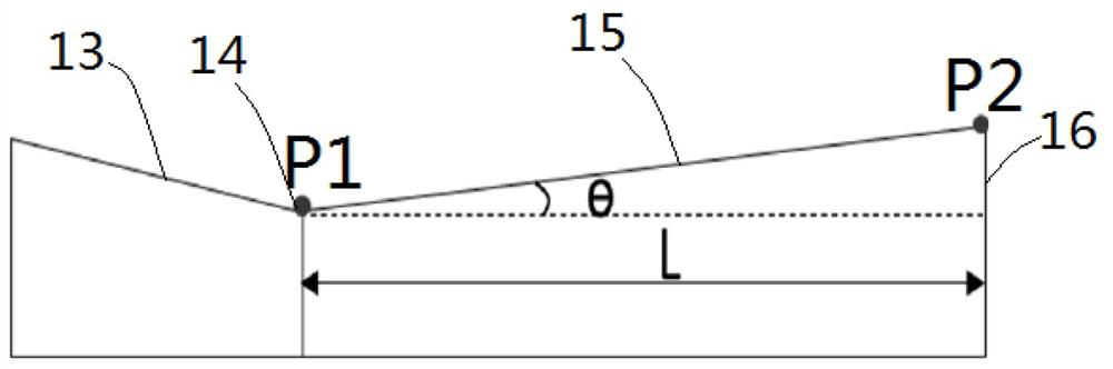
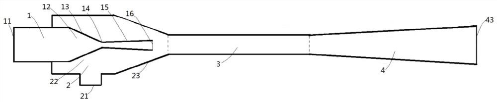
[0028] refer to figure 1 A work recovery system using an ejector according to an embodiment of the present invention will be introduced. For example, it may be a refrigeration device as an example. The work recovery system may include: a compressor 83 , the outlet of the compressor 83 is connected to the inlet of the condenser 82 downstream thereof, and the outlet of the condenser 82 is connected to the high-pressure fluid inlet 11 of the ejector 80 . On the other hand, the fluid outlet 43 of the injector 80 is connected with a separator 84 . Fluid exiting fluid outlet 43 of ejector 80 is separated in a separator wherein the gas phase returns to the inlet of compressor 83 and the liquid phase enters low pressure fluid inlet 21 of ejector 80 after passing valve 85 and evaporator 86 . In the illustrated embodiment, injector 80 is used as figure 1 As shown in the work recovery system, in alternative embodiments, the injector 80 can also be applied to other types of more complex...


PUM


Abstract

The invention provides an ejector for a heat recovery or work recovery system and the heat recovery or work recovery system. The ejector comprises a high-pressure fluid channel, a low-pressure fluid channel, a mixing chamber and a diffusion chamber, wherein the high-pressure fluid channel comprises a high-pressure fluid inlet and a high-pressure fluid nozzle; the low-pressure fluid channel comprises a low-pressure fluid inlet and a suction chamber surrounding the high-pressure fluid nozzle; the mixing chamber is in fluid communication with the high-pressure fluid channel and the low-pressure fluid channel; the diffusion chamber is arranged downstream of the mixing chamber; the high-pressure fluid nozzle sequentially comprises a contraction section, a throat portion and a diffusion section, and a high-pressure fluid outlet is limited at the tail end of the diffusion section; and the circumferential wall of the diffusion section is in an outwards-protruding arc shape in the longitudinal section. The ejector has higher efficiency.

Description

technical field [0001] The present invention relates to the field of heat recovery (heat recovery) or work recovery (work recovery) system, more specifically, the present invention relates to a kind of ejector for heat recovery or work recovery system and the heat recovery or work recovery system with such injector recycling system. Background technique [0002] Commercial heat recovery or work recovery systems, especially those requiring large differential pressures, use ejectors to improve efficiency. The ejector converts the pressure energy of the high-pressure fluid into kinetic energy, mixes it with the sucked low-pressure fluid, and provides the mixed medium-pressure fluid to the compressor inlet, thereby increasing the pressure of the compressor inlet fluid, thereby reducing the capacity of the compressor needs to improve system efficiency. [0003] Ejectors usually include high pressure fluid nozzles to convert high pressure fluid into high momentum fluid, low pres...

Claims


Application Information

Patent Timeline
IPC IPC(8): F25B27/02F25B9/08
CPCF25B27/02F25B9/08F04F5/24F04F5/46F04F5/54
Inventor 张薇P.韦尔马
Owner CARRIER CORP
Why Eureka
Try Eureka