Supercharge Your Innovation With Domain-Expert AI Agents!

Non-positive displacement type pump and liquid supply device

A positive displacement pump and pump housing technology, which is applied to non-volume pumps, non-variable volume pumps, liquid fuel feeders, etc. Increased discharge flow and other issues, to achieve the effect of reducing noise and suppressing decompression boiling

Pending Publication Date: 2021-09-21
MITSUBA CORP
View PDF13 Cites 0 Cited by
  • Summary
  • Abstract
  • Description
  • Claims
  • Application Information

AI Technical Summary

Problems solved by technology

That is, if the circumferential length of the seal portion is short, the amount of fuel sucked into the through flow path of the impeller increases correspondingly, so the discharge flow rate of the non-displacement pump increases.
On the other hand, if the circumferential length of the sealing portion is long, the amount of fuel sucked into the through passage of the impeller decreases correspondingly, so the discharge flow rate of the non-displacement pump decreases.

Method used


Image

  • Non-positive displacement type pump and liquid supply device
  • Non-positive displacement type pump and liquid supply device
  • Non-positive displacement type pump and liquid supply device

Examples


Embodiment Construction

[0034] Hereinafter, embodiments of the present invention will be described based on the drawings.

[0035] (liquid supply device)

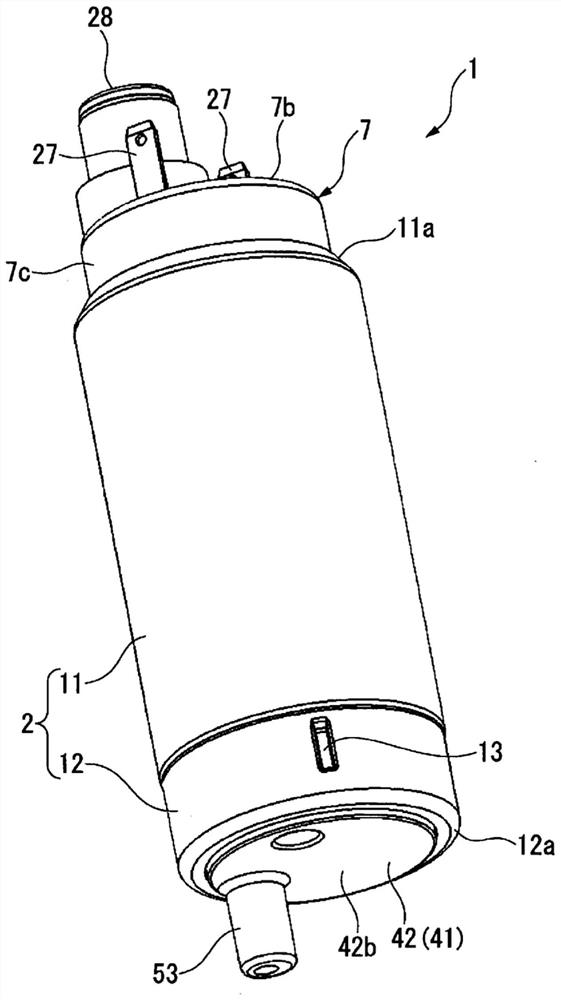
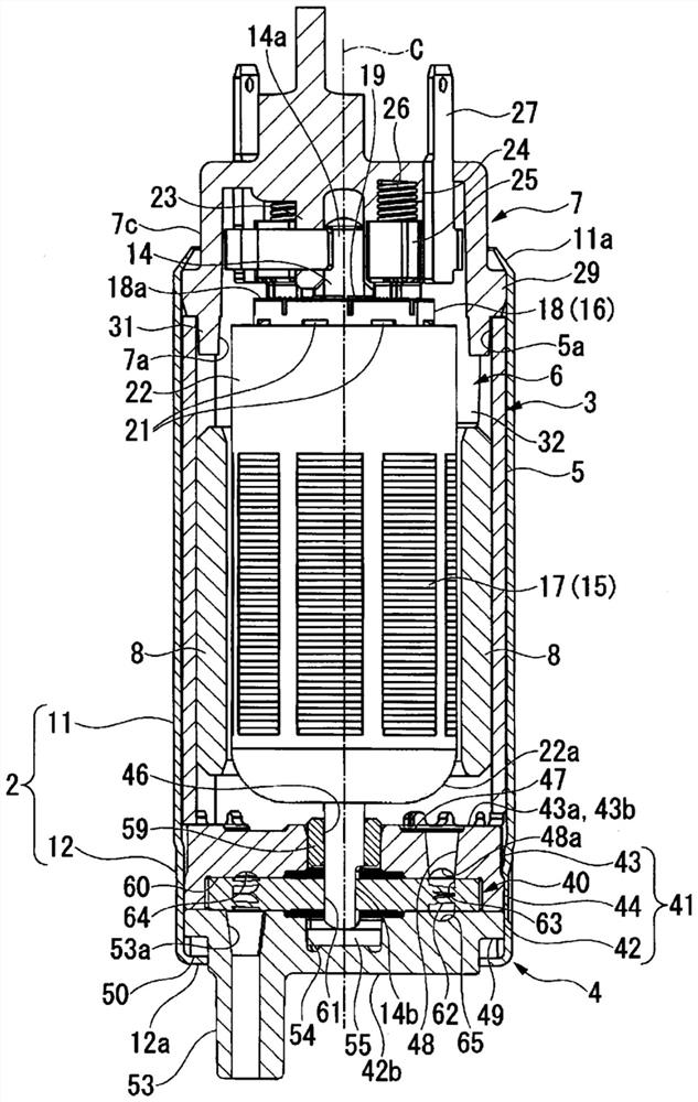
[0036] figure 1 It is a perspective view of the liquid supply device 1 . figure 2 is an axial sectional view of the liquid supply device 1 .

[0037] The liquid supply device 1 is used as a fuel pump for vehicles such as motorcycles and four-wheel vehicles. The liquid supply device 1 is a so-called in-tank type fuel pump arranged in a fuel tank not shown.

[0038] Such as figure 1 , figure 2 As shown, the liquid supply device 1 includes: a substantially cylindrical metal housing 2; The housing 2, the motor unit 3, and the pump unit 4 are arranged coaxially.

[0039] In the liquid supply device 1 , the pump unit 4 is used downward in the direction of gravity. Therefore, in the following description, the motor part 3 side may be referred to as the upper side, and the pump part 4 side may be referred to as the lower side. In addition, in t...


PUM

PropertyMeasurementUnit
Angleaaaaaaaaaa

Abstract

A pump unit (4), which is a non-positive displacement type pump provided in a liquid supply device (1), has a first seal section (66) and a second seal section (67) provided between an intake port (53) and a discharge port (48) in the circumferential direction of an impeller (40). An angle between the two straight lines connecting the circumferential ends of each seal portion (66, 67) and the center of rotation of the impeller (40) is 43 degrees or more and 47 degrees or less. Each seal portion (66, 67) has a size making it possible to close at least two through flow paths (63) between both ends in the circumferential direction.

Description

technical field [0001] The present invention relates to non-displacement pumps and liquid supply devices. Background technique [0002] The non-displacement pump includes a substantially disk-shaped impeller and a pump casing formed to cover the entire impeller. In the impeller, a plurality of blades are formed along the circumferential direction. A plurality of through-flow passages penetrating the impeller in the plate thickness direction are formed between the respective blade portions. The pump casing accommodates the impeller so that it can rotate freely. In addition, the pump casing has a suction port and a discharge port arranged on both sides of the impeller. [0003] Such a non-displacement pump is used, for example, as a liquid supply device (fuel pump) for vehicles such as motorcycles and four-wheeled vehicles. Such a liquid supply device is disposed in the fuel tank. [0004] With such a configuration, when the impeller is rotated, fuel enters the through fl...

Claims


Application Information

Patent Timeline
IPC IPC(8): F04D5/00F02M37/08F02M37/10F04D29/16F04D29/66
CPCF02M37/10F02M37/08F04D5/002F04D5/008F04D29/188F04D29/165F04D29/669
Inventor 莲子多津也堀底伸一郎竹内直树大村知司小林龙太郎
Owner MITSUBA CORP
Features
  • R&D
  • Intellectual Property
  • Life Sciences
  • Materials
  • Tech Scout
  • Unparalleled Data Quality
  • Higher Quality Content
  • 60% Fewer Hallucinations
Learn More