Protective mask

A protective mask, mask technology, applied in the direction of respiratory masks, respiratory protection devices, respiratory protection containers, etc.

Inactive Publication Date: 2021-09-24
贝特霍尔德 W 西曼
View PDF10 Cites 2 Cited by
  • Summary
  • Abstract
  • Description
  • Claims
  • Application Information

AI Technical Summary

Problems solved by technology

[0007] However, the prior art has always had disadvantages, especially with rega

Method used


Image

  • Protective mask
  • Protective mask
  • Protective mask

Examples


Embodiment Construction

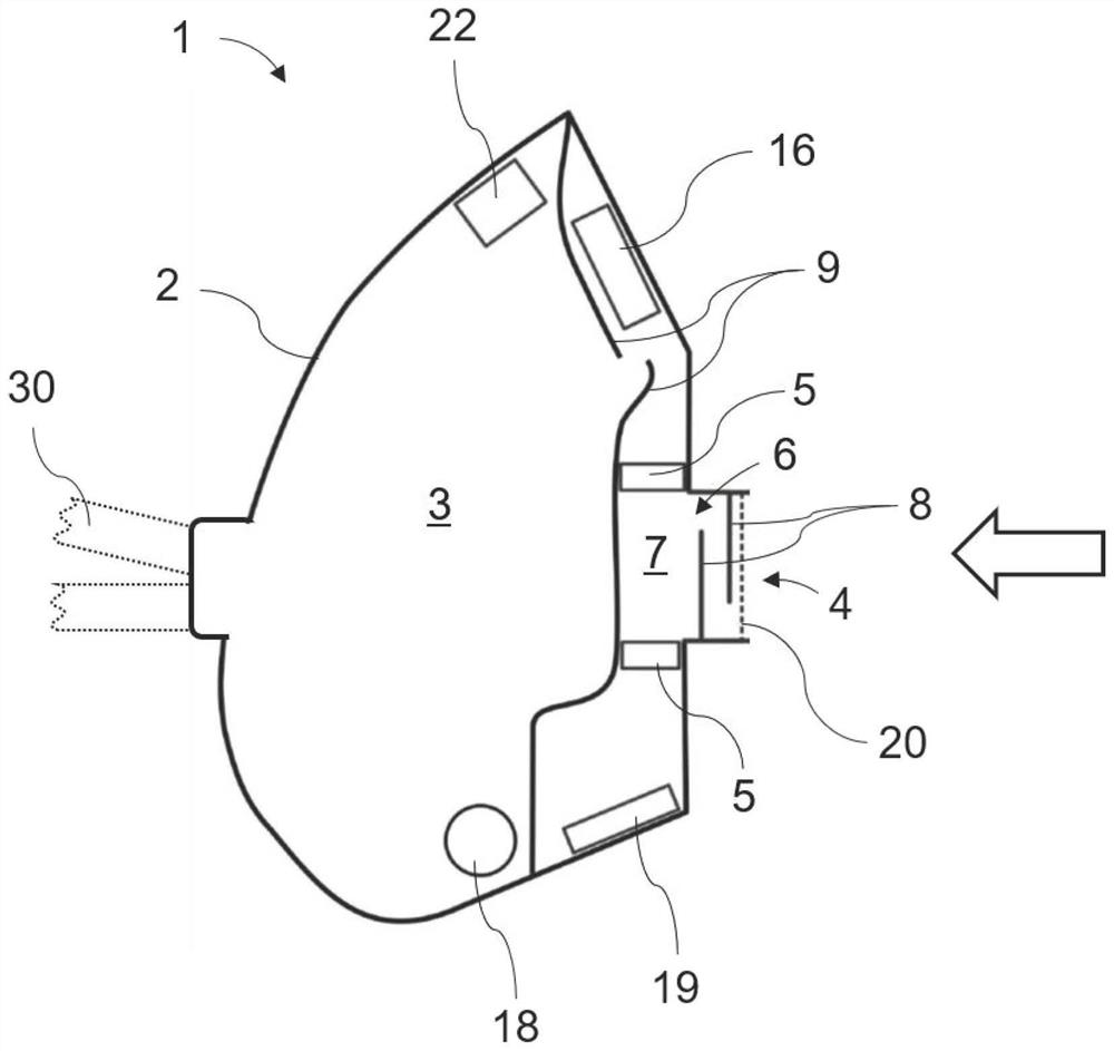
[0060] figure 1 An exemplary basic construction of the protective mask 1 according to the invention is shown on the basis of a significantly simplified schematic sectional illustration. The protective mask 1 has a mask body 2 defining a breathing chamber 3 for receiving the user's mouth and nose. Air can be introduced into the breathing chamber 3 from the outside (shown here by a thick arrow) via the breathing opening 4 , which is fluidly connected to the breathing chamber 3 . The filter device 20 is responsible for separating dust particles from the breathing air when entering the protective mask 1 . The protective mask 1 can be worn in front of the face by means of a holding device 30 not shown in detail here, for example an elastic strap extending around the user's head.

[0061] Located between the breathing port 4 and the breathing chamber 3 is a radiation chamber 6 with a chamber interior 7 which forms part of the fluid connection between the breathing port 4 and the b...


PUM


Abstract

The invention relates to a protective mask having a mask main body which defines a breathing chamber for receiving the mouth and/or nose of a user, a breathing opening which is fluidically connected to the breathing chamber, and at least one ultraviolet-emitting light source by means of which ultraviolet radiation rays can be applied to the breathing air when the breathing air flows through the fluid connection. A radiation chamber is arranged between the breathing opening and the breathing chamber, and the radiation chamber has a chamber interior space forming at least part of the fluid connection. The light source emitting ultraviolet rays is arranged to at least partially apply ultraviolet rays to the interior space of the chamber.

Description

technical field [0001] The present invention relates to a protective mask for preventing infection. Such protective masks are used in particular in the field of personal protective equipment (PSA). Background technique [0002] Protective masks are an essential part of personal protective equipment for medical personnel against the respiratory transmission of infectious diseases and, in certain cases, can advantageously also reduce the risk of infection among ordinary citizens. [0003] As a minimum protection against infectious diseases, so-called particle filtering half masks ("Filtering Face Piece" in English, "Filtering Face Piece", abbreviated "FFP") are primarily used. FFP type masks have a preformed mask body and filter media integrated in the mask body, which is worn over the mouth and nose to isolate the face from the ambient space. Such particle masks have been disclosed, for example, in patent documents EP 2298419A1 and EP 3375308A1. [0004] In order to be abl...

Claims


Application Information

Patent Timeline
IPC IPC(8): A62B7/10A62B9/02A62B18/02A62B18/08A62B18/10A62B23/02A61L9/20
CPCA62B18/02A62B18/08A62B23/02A62B7/10A62B9/022A62B18/10A61L9/20A62B18/025
Inventor 贝特霍尔德·W·西曼
Owner 贝特霍尔德 W 西曼
Why Eureka
Try Eureka