DIY toy model bottom plate cleaning equipment
A technology for cleaning equipment and bottom plates, which is applied to cleaning methods using tools, cleaning methods and utensils, and cleaning methods using liquids, etc., which can solve the problems of time-consuming, labor-intensive, and large-scale operations, and achieve the effect of improving cleaning quality
- Summary
- Abstract
- Description
- Claims
- Application Information
AI Technical Summary
Problems solved by technology
Method used
Image
Examples
Embodiment 1
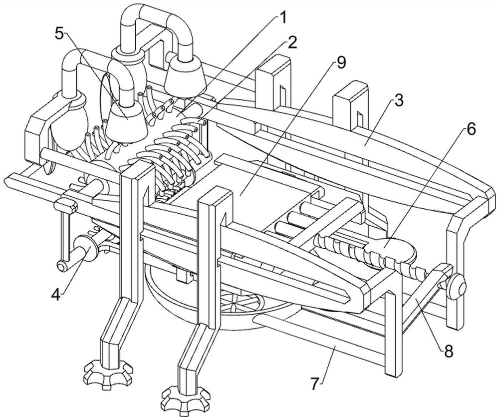
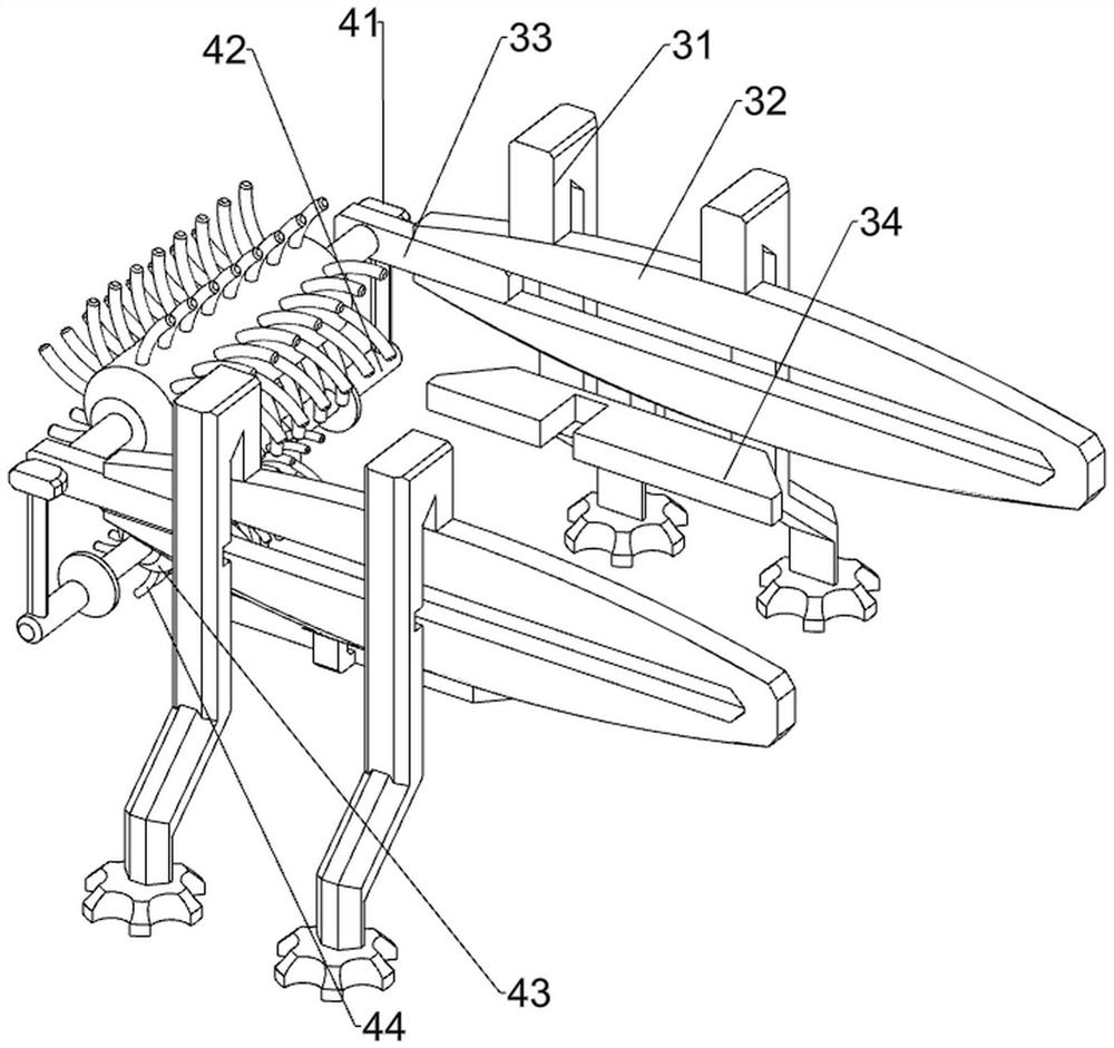
[0024] A DIY toy model bottom plate cleaning equipment, such as figure 1 and figure 2 As shown, it includes a first drum 1, a first cleaning strip 2, a placement guide structure 3 and a cleaning mechanism 4. The device is provided with a placement guide structure 3, and the left side of the placement guide structure 3 is rotatably provided with a first drum 1. , a plurality of first cleaning strips 2 are arranged on the first drum 1 , and a cleaning mechanism 4 is arranged on the left side of the placement guide structure 3 , and the cleaning mechanism 4 is located below the first drum 1 .
[0025] The placement guide structure 3 includes a support seat 31 , a guide groove plate 32 , a sliding block 33 and a bottom plate placement block 34 . The support seat 31 is symmetrically arranged in the front and rear, the upper and inner sides of the support seat 31 are provided with a guide groove plate 32 , and the bottom of the guide groove plate 32 is provided. A bottom plate pla...
Embodiment 2
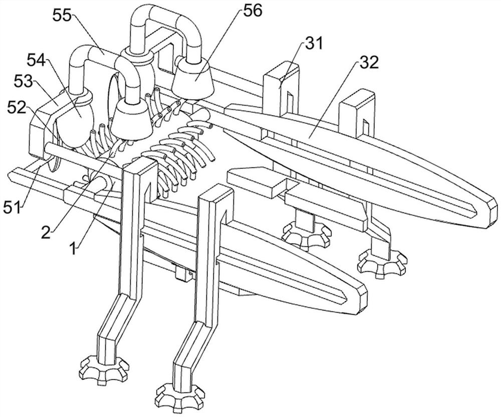
[0029] On the basis of Example 1, as image 3 and Figure 4 As shown, a flushing mechanism 5 is also included. The flushing mechanism 5 includes a support frame 51, a toggle block 52, a mounting bracket 53, a rubber water storage bag 54, a water outlet pipe 55 and a spray head 56. The left side of the sliding block 33 is provided with a support frame 51. A toggle block 52 is connected to the inner side of the support frame 51, a mounting bracket 53 is provided on the left side of the upper part of the support base 31, and a rubber water storage bag 54 is provided on the inner side of the mounting bracket 53. The top of the rubber water storage bag 54 is provided with a water outlet pipe 55. A spray head 56 is connected to the other end of the water outlet pipe 55 .
[0030] The sliding block 33 moves to the right through the support frame 51 to drive the toggle block 52 to move to the right and squeeze the rubber water storage bag 54. The clean water in the rubber water stora...
Embodiment 3
[0032] On the basis of Example 2, as Figure 5 to Figure 7 As shown, it also includes a bottom feeding mechanism 6, and the bottom feeding mechanism 6 includes a connecting frame 61, an arc block 62, a circular block 63, a connecting rod 64, a support block 65 and a return spring 66. The inner side of the connecting block 41 A connecting frame 61 is connected between them, and the top of the connecting frame 61 is provided with an arc-shaped block 62. The arc-shaped block 62 is located on the right side of the second drum 43. The left part of the bottom plate placing block 34 is slidably provided with a support block 65. A return spring 66 is connected between the inner walls of the bottom plate placing block 34 , a connecting rod 64 is provided at the bottom of the support block 65 , and a circular block 63 is provided on the right side of the connecting rod 64 .
[0033] It also includes a collecting and filtering mechanism 7. The collecting and filtering mechanism 7 include...
PUM
 Abstract
Description
Claims
Application Information
 - R&D
- Intellectual Property
- Life Sciences
- Materials
- Tech Scout
- Unparalleled Data Quality
- Higher Quality Content
- 60% Fewer Hallucinations
Browse by: Latest US Patents, China's latest patents, Technical Efficacy Thesaurus, Application Domain, Technology Topic, Popular Technical Reports.
© 2025 PatSnap. All rights reserved.Legal|Privacy policy|Modern Slavery Act Transparency Statement|Sitemap|About US| Contact US: help@patsnap.com


