Dry cleaning device and dry cleaning method

A technology for cleaning equipment and cleaning agents, applied in cleaning methods and utensils, cleaning methods using gas flow, cleaning with electrostatic methods, etc., can solve problems such as damage and scratches, and achieve high cleaning quality.

Inactive Publication Date: 2007-09-05
RICOH KK
View PDF5 Cites 20 Cited by
  • Summary
  • Abstract
  • Description
  • Claims
  • Application Information

AI Technical Summary

Problems solved by technology

[0010] Since the grinding object and the drying medium are put into a tumbler jar for agitation, as in Patent Document 2, there are concerns about scratching and damage due to the nature of the grinding object

Method used


Image

  • Dry cleaning device and dry cleaning method
  • Dry cleaning device and dry cleaning method
  • Dry cleaning device and dry cleaning method

Examples


no. 1 example

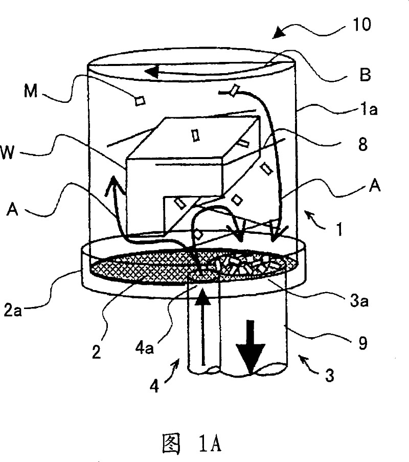
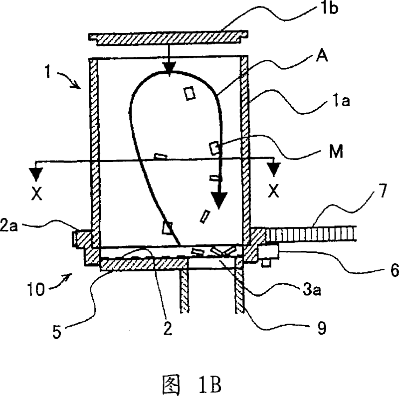
[0080] A first embodiment of the present invention will be described with reference to FIGS. 1A and 1B and FIGS. 2A and 2B. In the following, each unit of the device will be explained first.

[0081] The cleaning box 10 is made by using a disc-shaped cover portion 1b at the top, a cylindrical side wall portion 1a, a disc-shaped mesh member 2 at the bottom, a mesh member cover 5 partially covering the mesh member 2, and a mesh member for holding the mesh member. The holding unit 2a of the piece 2, which together form a closed space, except for leaving a certain opening.

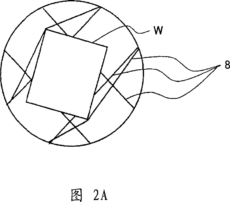
[0082] The side wall portion 1a is a cylindrical member fixedly mounted to the holding unit 2a. When the holding unit 2a rotates, the side wall portion 1a also rotates jointly with the cover portion 1b. The side wall portion 1a is provided with a workpiece holding unit 8, which will be described in detail below.

[0083] The side wall portion 1a is slidably engaged with the holding unit 2a so that the side ...

no. 2 example

[0126] 7A and 7B show the construction of the second embodiment of the present invention. Fig. 7A is a plan view of the cleaning tank, and Fig. 7B is a partially cutaway side view.

[0127] The direction of rotation D of the suction duct 9 , the base plate 11 , the support column 12 , the upper plate 13 , the rotation shaft bushing 14 , the rotary drive unit 15 and the suction duct 9 is shown. In this embodiment, the grid 2 is fixed, while the suction opening and the inlet are rotated. Hereinafter, each unit will be explained.

[0128] The mesh member 2 as a separation unit does not allow the passage of the cleaning agent M, but allows the passage of the dust which has not been removed. The grid 2 has a cylindrical basket shape and is fixedly mounted to the upper plate 13 . The mesh cover 5 covers the outer periphery of the cylindrical mesh 2, thereby separating the clean box 10 from the outside air. The mesh cover 5 is rotated while its inner wall is positioned adjacent t...


PUM


Abstract

A dry cleaning apparatus which causes cleaning agent to fly in a gas current to impact an object to be cleaned so as to remove extraneous substance attached to the object includes a cleaning tank defining an interior space for accommodating the cleaning agent and the object with the attached extraneous substance, an inflow unit configured to guide a gas current into the cleaning tank through an inlet, an aspiration unit configured to discharge gas from the cleaning tank through an aspiration opening, and a separation unit disposed between the interior space of the cleaning tank and both the inflow unit and the aspiration unit, the separation unit having openings that allow the gas and the extraneous substance to pass through but do not allow the cleaning agent to pass through, wherein the inlet, the aspiration opening, and the separation unit are configured such that relative motion is created between the separation unit and both the inlet and the aspiration opening.

Description

technical field [0001] The present invention generally relates to a device for removing dust and fine particles adhering to objects to be cleaned using solid cleaning agents without using water or solvents, and more particularly to a dry cleaning device for cleaning parts of complex shapes, which The part has toner particles (average diameter of 5 to 10 micrometers) attached to the part used in electrophotographic equipment such as copiers and laser printers. The present invention is applicable to cleaning, grinding, deburring, and coating removal of toner processing equipment. Background technique [0002] Manufacturers of office equipment, such as copiers, facsimile machines, and printers, are actively conducting recycling activities in which used products or component units are collected from users and then disassembled, cleaned, and assembled again to be used as Components or raw materials are recycled to realize a resource recycling society. In order to recycle compon...

Claims


Application Information

Patent Timeline
Patent Type & Authority Applications(China)
IPC IPC(8): B08B5/00
CPCB08B7/02B08B5/00B08B6/00
Inventor 冈本洋一渕上明弘武藤敏之平泽友康佐藤达哉
Owner RICOH KK
Why Eureka
Try Eureka