Air conveying energy-saving device for medical mechanism

A technology for medical institutions and air transportation, applied in the directions of space heating and ventilation details, applications, and piping arrangements, it can solve problems such as the inability to switch internal flow channels, the inability to adjust heat exchange efficiency, and the limitation of heat exchange locations, and achieve structural adjustment. Simple and convenient operation, improve heat exchange performance, and reduce the effect of later use costs

Active Publication Date: 2021-09-24
江苏环亚节能技术服务有限公司
View PDF5 Cites 1 Cited by
  • Summary
  • Abstract
  • Description
  • Claims
  • Application Information

AI Technical Summary

Problems solved by technology

[0006] The technical problem to be solved by the present invention is: in order to solve the problems existing in the above-mentioned background technology, provide an improved air delivery energy-saving device for medical institutions, and solve the problem that the current medical clean air-conditioning devices on the market need to be discharged and discharged through independent pipelines. Exhaust air, in order to improve energy saving and environmental protection performance, it is necessary to install a heat exchanger between the delivery pipe and the output pipe, the heat exchange position is limited, the heat exchange efficiency cannot be adjusted, and the internal flow channel cannot be switched, resulting in a very limited application range

Method used


Image

  • Air conveying energy-saving device for medical mechanism
  • Air conveying energy-saving device for medical mechanism
  • Air conveying energy-saving device for medical mechanism

Examples


Embodiment Construction

[0027] The present invention is described in further detail now in conjunction with accompanying drawing. These drawings are all simplified schematic diagrams, which only illustrate the basic structure of the present invention in a schematic manner, so they only show the configurations related to the present invention.

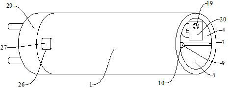
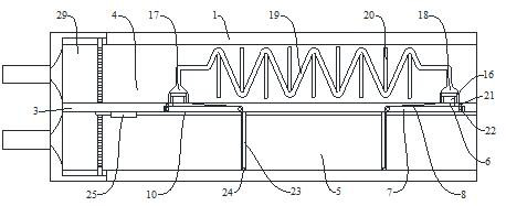
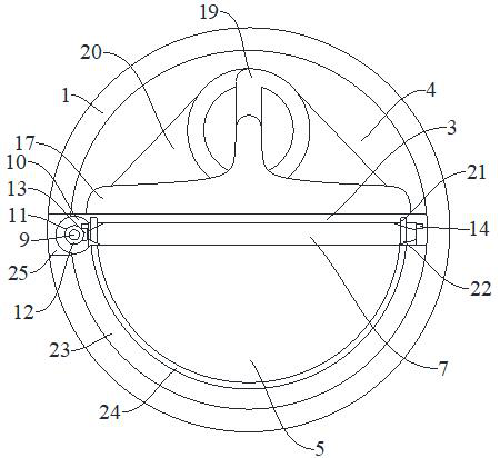
[0028] figure 1 , figure 2 and image 3 The shown air delivery energy-saving device for medical institutions includes an air delivery conduit 1 and a regulating motor 2 for coordinating with the air conditioning system of the medical institution. The interior of the air delivery conduit 1 is divided into upper The air delivery channel 4 and the lower air delivery channel 5, the middle separation partition 3 is provided with a plurality of internal air guide ports 6 for connecting the upper delivery flow channel 4 and the lower delivery flow channel 5, and the middle separation partition 3. The lower surface is located at the lower opening of the inner air ...


PUM


Abstract

The invention relates to the technical field of medical air conveying and conditioning energy-saving equipment, in particular to an air conveying energy-saving device for a medical mechanism. The device comprises an air conveying guide pipe and an adjusting motor which are used for cooperating with an air conditioning system of the medical mechanism. According to the air conveying energy-saving device for the medical mechanism, the interior of the air conveying guide pipe is divided into an upper air conveying flow channel and a lower air conveying flow channel through a middle separation partition plate, a turnover closing cover plate used for switching heat exchange flow channels is installed on the middle separation partition plate, so that the flow direction of the lower air conveying flow channel is adjustable, an input pipe and an output pipe are integrated in the same pipeline, so that the whole-process heat exchange capacity is achieved, the heat exchange performance is greatly improved, and the device is more energy-saving and environment-friendly; and a first permanent magnet strip is fixed to the inner side of a bottom storage groove, a second permanent magnet strip is fixed to the turnover closing cover plate, third permanent magnet strips are installed in lateral sealing frames, the fitness during storage and assembling can be improved, and therefore the flatness and sealing performance of the inner surface are improved.

Description

technical field [0001] The invention relates to the technical field of medical air conveying adjustment energy-saving equipment, in particular to an air conveying energy-saving device for medical institutions. Background technique [0002] Hospital clean air conditioner is an indoor air purification equipment that uses physical filtration to clean and disinfect air. It is composed of blower, filter, and DDC control system. It is mainly used in clean air-conditioned rooms in hospitals, clean laboratories, clean machine rooms, hospital waiting rooms, medical staff offices, lounges and other places. [0003] It can freely set the cleanliness, temperature, and humidity: by adjusting the DDC setting, the air cleanliness can be set freely, and it can meet different air cleanliness requirements from general surgery to transplantation. [0004] The indoor temperature and humidity sensor is used to automatically and intelligently adjust the indoor temperature and humidity to meet th...

Claims


Application Information

Patent Timeline
Patent Type & Authority Applications(China)
IPC IPC(8): F24F3/163F24F13/02F24F13/30
CPCF24F3/163F24F13/02F24F13/30
Inventor 吴剑锋张万乾陈文建孙小伟冯慧亮冯芳承吴佳艳王丽霞刘学皎李儒鹏
Owner 江苏环亚节能技术服务有限公司
Why Eureka
Try Eureka