
Oxygen supply abnormity treatment equipment for intensive care unit

An intensive care unit and abnormal handling technology, applied in the direction of drug equipment, other medical equipment, respirators, etc., can solve the problems of high safety hazard, patient danger, untimely dumping and other problems, to avoid waste, control the use cost, The effect of convenient use of the same name

Active Publication Date: 2021-09-28
NINGBO RUNYES MEDICAL INSTR
View PDF4 Cites 0 Cited by
  • Summary
  • Abstract
  • Description
  • Claims
  • Application Information

AI Technical Summary

Problems solved by technology

[0002] In the process of medical rescue, ventilators are often used to help patients with assisted breathing, and during the use of ventilators, especially in medical sick rooms, due to the relatively low ambient temperature in hospitals, the exhaled gas will When the temperature of the breathing tube is low, condensed water will be generated in the breathing tube. The accumulated condensed water will not only affect the delivery of oxygen, but if the condensed water enters the patient's respiratory tract along the tube, it will cause dyspnea and bring harm to the patient. Danger
[0003] At present, breathing tubes are mostly attached figure 2 The shown bellows-type breathing tube 1 is used to facilitate the condensation of exhaled gas, and at the same time, the condensed water is collected through the water collection cup, but it is prone to the problem of untimely dumping and disposal. In this case, too much condensed water is easy to enter the pipeline It is inhaled into the respiratory tract, and it is easy to bring danger to the patient, especially for high-risk patients in the intensive care unit, whose demand for oxygen is more stringent, and the safety hazard is higher. Therefore, we propose a treatment device for abnormal oxygen supply in the intensive care unit

Method used


Image

  • Oxygen supply abnormity treatment equipment for intensive care unit
  • Oxygen supply abnormity treatment equipment for intensive care unit
  • Oxygen supply abnormity treatment equipment for intensive care unit

Examples


Embodiment Construction

[0028] The following will clearly and completely describe the technical solutions in the embodiments of the present invention with reference to the accompanying drawings in the embodiments of the present invention. Obviously, the described embodiments are only some of the embodiments of the present invention, not all of them. Based on the embodiments of the present invention, all other embodiments obtained by persons of ordinary skill in the art without making creative efforts belong to the protection scope of the present invention.

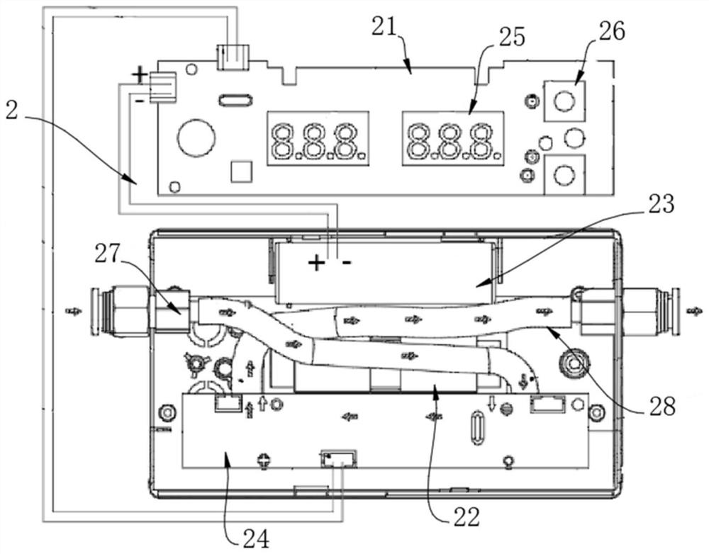
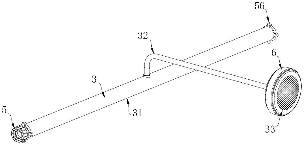
[0029] see Figure 1-7 , the present invention provides a technical solution: a kind of oxygen supply abnormal treatment equipment for intensive care unit, including oxygen monitor 2, and the oxygen monitor 2 includes a housing 21; Device 22, battery 23, high-precision humidity sensor 24 and electronic display screen 25, described battery 23 is electrically connected with microprocessor 22, high-precision humidity sensor 24 and electronic display...


PUM


Abstract

The invention discloses oxygen supply abnormity treatment equipment for an intensive care unit. The oxygen supply abnormity treatment equipment comprises an oxygen monitor and a drying component, wherein the oxygen monitor is used for monitoring the oxygen humidity in a breathing tube; the drying component is arranged on the outer side of the breathing tube, and is in signal connection with the oxygen monitor; and the drying component is started to dry condensed water in the breathing tube when the oxygen monitor monitors that the oxygen humidity is greater than a preset value. According to the oxygen supply abnormity treatment equipment for the intensive care unit, condensed water can be automatically dried when condensed water appears in an oxygen supply pipeline of the intensive care unit and is continuously increased to affect safe oxygen supply, and the condensed water in the breathing pipeline is quickly dried and volatilized, so that the danger caused by the fact that the condensed water enters the respiratory tract of a patient is effectively avoided, and safe and effective intensive care nursing use is ensured.

Description

technical field [0001] The invention relates to the technical field of oxygen supply equipment for intensive care units, in particular to an abnormal treatment equipment for oxygen supply for intensive care units. Background technique [0002] In the process of medical rescue, ventilators are often used to help patients with assisted breathing, and during the use of ventilators, especially in medical sick rooms, due to the relatively low ambient temperature in hospitals, the exhaled gas will When the temperature of the breathing tube is low, condensed water will be generated in the breathing tube. The accumulated condensed water will not only affect the delivery of oxygen, but if the condensed water enters the patient's respiratory tract along the tube, it will cause dyspnea and bring harm to the patient. Danger. [0003] At present, breathing tubes are mostly attached figure 2 The shown bellows-type breathing tube 1 is used to facilitate the condensation of exhaled gas, a...

Claims


Application Information

Patent Timeline
IPC IPC(8): A61M16/08A61M16/10A61M16/00
CPCA61M16/0003A61M16/08A61M16/1075A61M16/021A61M2205/362
Inventor 徐依徐步光
Owner NINGBO RUNYES MEDICAL INSTR
Learn More