
Efficient cyclone separator with built-in impeller structure

A technology of cyclone separator and impeller, which is applied in the direction of swirl devices and devices whose axial direction of swirl can be reversed, etc., which can solve the problems of discharge and the reduction of the separation effect of cyclone separators, and achieve the effect of improving the separation effect

Active Publication Date: 2021-09-28
CHINA TOBACCO JIANGXI IND CO LTD
View PDF15 Cites 1 Cited by
  • Summary
  • Abstract
  • Description
  • Claims
  • Application Information

AI Technical Summary

Problems solved by technology

However, the existing impeller-type cyclone separator still has the possibility or situation that some or a small amount of particles will be discharged from the exhaust section with the air flow, resulting in a reduction in the separation effect of the cyclone separator

Method used


Image

  • Efficient cyclone separator with built-in impeller structure
  • Efficient cyclone separator with built-in impeller structure
  • Efficient cyclone separator with built-in impeller structure

Examples


Embodiment Construction

[0019] In order to make the purpose, technical solutions and advantages of the embodiments of the present invention clearer, the technical solutions in the embodiments of the present invention will be clearly and completely described below in conjunction with the drawings in the embodiments of the present invention. Obviously, the described embodiments It is a part of embodiments of the present invention, but not all embodiments. Based on the embodiments of the present invention, all other embodiments obtained by persons of ordinary skill in the art without creative efforts fall within the protection scope of the present invention.

[0020] The present invention will be described in further detail below in conjunction with the accompanying drawings.

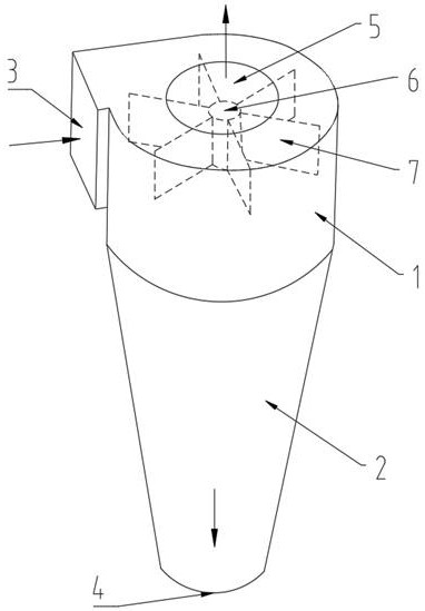
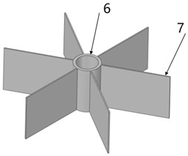
[0021] Such as Figure 1-4 As shown, a high-efficiency cyclone separator with a built-in impeller structure includes a cylinder body 1, a cone body 2, an air inlet section 3, a discharge port 4, and an exhaust section 5. The low...


PUM


Abstract

The invention discloses an efficient cyclone separator with a built-in impeller structure. The efficient cyclone separator comprises a cylinder body (1), a conical cylinder body (2), an air inlet section (3), a discharging opening (4) and an exhaust section (5), wherein the impeller structure is arranged in an inner cavity of the cylinder body, and the impeller structure rotates under the impact of air flow and particulate flow. The efficient cyclone separator is characterized in that the impeller structure comprises a first sleeve pipe (6), first blades (7), a rotating shaft (8), second blades (11) and a second sleeve pipe (12); the rotating shaft is sleeved with the first sleeve pipe and the second sleeve pipe, a plurality of first blades which are evenly distributed are arranged on the periphery of the first sleeve pipe, and a plurality of second blades which are evenly distributed are arranged on the periphery of the second sleeve pipe; and the second blades are located above the first blades, and the radius of each second blade is greater than that of each first blade. According to the cyclone separator, under the blocking and turning-back effects of the second blades, the possibility or the outflow amount of particulate matter discharged from the exhaust section can be reduced / restrained, and therefore the separation effect of the cyclone separator is improved.

Description

technical field [0001] The invention relates to the technical field of cyclone separators, in particular to a high-efficiency cyclone separator with a built-in impeller structure. Background technique [0002] A cyclone separator is a device used to separate gases and solids. Such as Figure 1-2 As shown, the existing cyclone separator with a built-in impeller structure includes a cylinder body 1, a cone body 2, an air inlet section 3, a discharge port 4, and an exhaust section 5. The lower end of the cylinder body 1 is connected with a cone Cylinder 2, the lower end of the cone 2 has a discharge port 4, the air inlet section 3 is substantially tangent to the circumference of the cylinder 1, and the end of the cylinder 1 away from the cone 2 is connected to an exhaust Section 5, the inner cavity of the cylinder 1 is provided with an impeller structure, the impeller structure includes a casing 6, blades 7, and a plurality of evenly distributed blades 7 are arranged on the ou...

Claims


Application Information

Patent Timeline
IPC IPC(8): B04C5/00B04C5/103
CPCB04C5/00B04C5/103
Inventor 许冰洋杨俊杰万宇超徐志强余东詹壁林顾丛汇赵海超
Owner CHINA TOBACCO JIANGXI IND CO LTD
Features
  • Generate Ideas
  • Intellectual Property
  • Life Sciences
  • Materials
  • Tech Scout
  • Unparalleled Data Quality
  • Higher Quality Content
  • 60% Fewer Hallucinations
Learn More