
Slow recovery mechanism, locking slow recovery device and winding device

A recovery mechanism and recovery device technology are applied in the fields of slow recovery mechanism, locking slow recovery device and winding device, which can solve the problem of damage to tools connected to the winding device, endangering the safety of users, and affecting the recovery of flexible materials by the winding device. Process and other issues to achieve the effect of convenient recycling

Pending Publication Date: 2021-09-28
士商(湖州)精密技术有限公司
View PDF0 Cites 0 Cited by
  • Summary
  • Abstract
  • Description
  • Claims
  • Application Information

AI Technical Summary

Problems solved by technology

[0002] When flexible materials such as tubes and spools are recycled through the spool that can be automatically recovered, the speed at which the flexible materials are recycled into the spool will gradually increase. If the recovery speed of flexible materials is too high, it will endanger the safety of users and cause winding. Therefore, in the prior art, the slow recovery mechanism is set to rub against the winding device to slow down the recovery speed of the flexible material by the winding device, thereby ensuring the safe use of the winding device, but the existing technology In this case, even if the recovery speed of the flexible material by the winder is small, when it is in the safe speed range, the slow recovery mechanism will rub against the winder, which will slow down the recovery speed of the flexible material by the winder, so that the slow recovery mechanism will Affects the recycling process of flexible materials by the winder, making the recycling of flexible materials not convenient enough

Method used


Image

  • Slow recovery mechanism, locking slow recovery device and winding device
  • Slow recovery mechanism, locking slow recovery device and winding device
  • Slow recovery mechanism, locking slow recovery device and winding device

Examples


Embodiment Construction

[0031] The following will clearly and completely describe the technical solutions in the embodiments of the present invention with reference to the accompanying drawings in the embodiments of the present invention. Obviously, the described embodiments are only part of the embodiments of the present invention, not all of them. Based on the embodiments of the present invention, all other embodiments obtained by persons of ordinary skill in the art without creative efforts fall within the protection scope of the present invention.

[0032] It should be noted that all directional indications (such as up, down, left, right, front, back...) in the embodiments of the present invention are only used to explain the relationship between the components in a certain posture (as shown in the accompanying drawings). Relative positional relationship, movement conditions, etc., if the specific posture changes, the directional indication will also change accordingly. In addition, the descripti...


PUM


Abstract

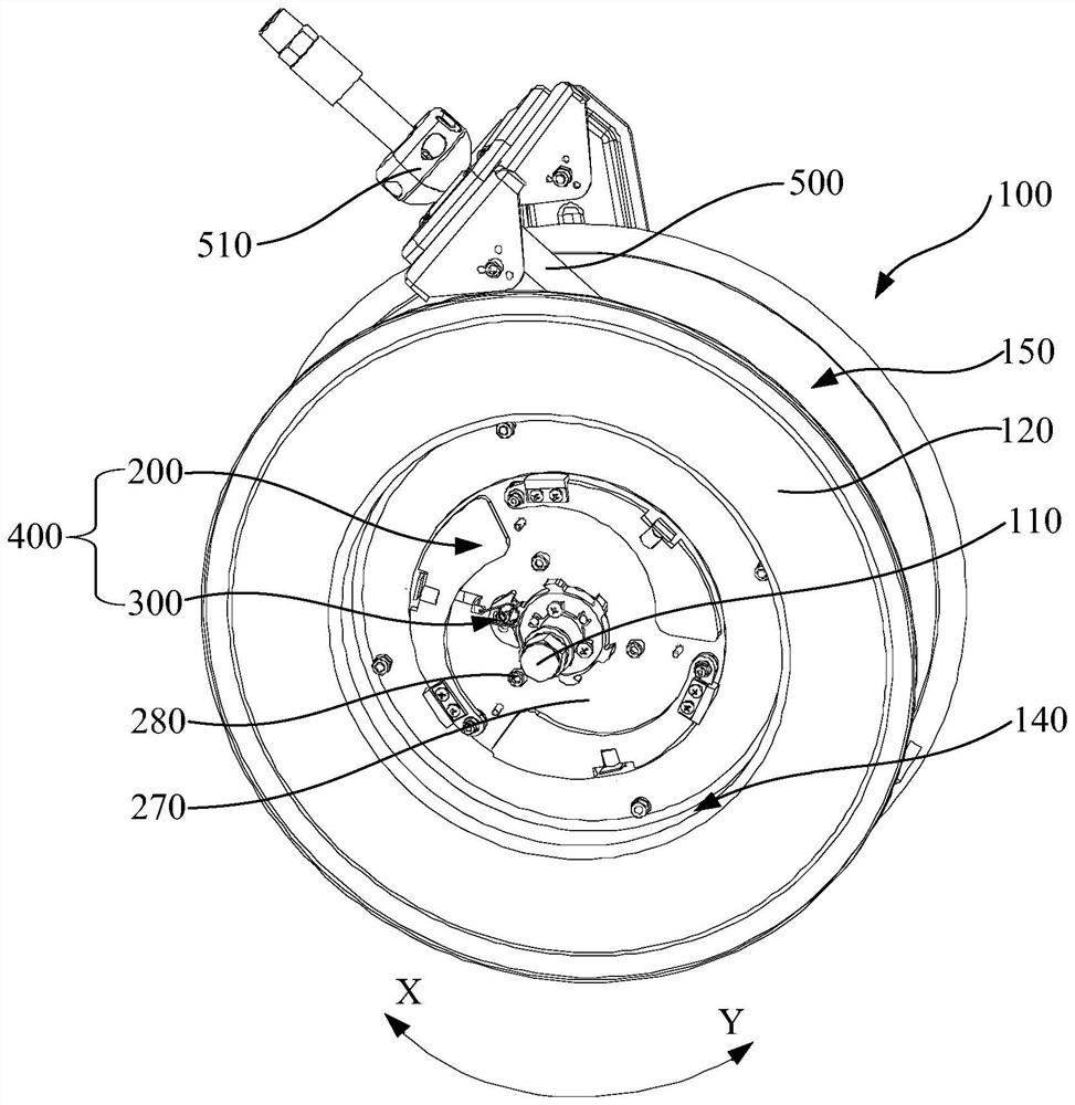
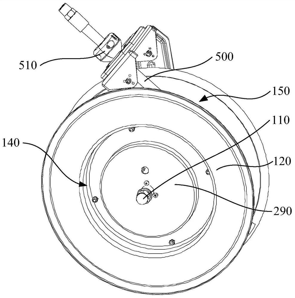
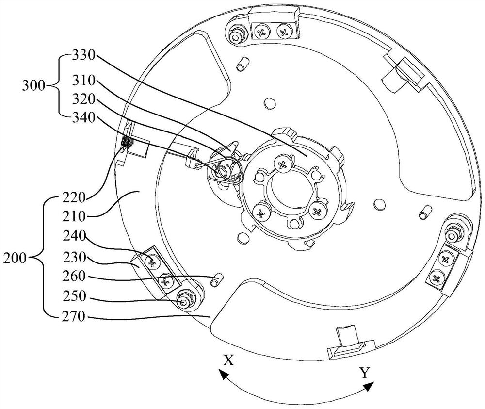
The invention discloses a slow recovery mechanism, a locking slow recovery device and a winding device. The slow recovery mechanism is used for being matched with a winder, the winder comprises a main shaft and a main body, the main body rotationally sleeves the main shaft, the main body can rotate around the main shaft so as to wind or unwind a flexible material, and the slow recovery mechanism comprises a blocking part, a speed reduction part and a first elastic part; the speed reduction part is rotationally arranged on the main body and located in the blocking part, when the main body rotates around the main shaft in a first direction to wind the flexible material, the speed reduction part can rotate relative to the main body in a second direction opposite to the first direction so as to be close to the blocking part, and the speed reduction part can make contact with the blocking part and generate friction with the blocking part to reduce the rotation speed of the main body in the first direction; and the first elastic part is arranged on the main body, is connected with the speed reduction part and is used for applying elastic acting force to the speed reduction part, and the elastic acting force is used for preventing the speed reduction part from rotating in the second direction.

Description

technical field [0001] The invention relates to the field of recovery of pipe windings and wire devices, in particular to a slow recovery mechanism, a locking slow recovery device and a winding device. Background technique [0002] When flexible materials such as tubes and spools are recycled through the spool that can be automatically recovered, the speed at which the flexible materials are recycled into the spool will gradually increase. If the recovery speed of flexible materials is too high, it will endanger the safety of users and cause winding. Therefore, in the prior art, the slow recovery mechanism is set to rub against the winding device to slow down the recovery speed of the flexible material by the winding device, thereby ensuring the safe use of the winding device, but the existing technology In this case, even if the recovery speed of the flexible material by the winder is small, when it is in the safe speed range, the slow recovery mechanism will rub against th...

Claims


Application Information

Patent Timeline
Patent Type & Authority Applications(China)
IPC IPC(8): B65H75/38B65H75/44
CPCB65H75/38B65H75/4457B65H75/4442B65H2701/30B65H2701/33B65H75/4447B65H75/4434B65H75/4428
Inventor 葛贵中邹兴
Owner 士商(湖州)精密技术有限公司
Learn More