Switch

A technology of switches and current collectors, applied in the direction of electric switches, electrical components, circuits, etc., can solve problems such as electronic controller system disturbances

Pending Publication Date: 2021-09-28
TIANJIN SVRUI INTELLIGENT ELECTRICAL CO LTD
View PDF0 Cites 0 Cited by
  • Summary
  • Abstract
  • Description
  • Claims
  • Application Information

AI Technical Summary

Problems solved by technology

[0003] System perturbation problem in the electronic controller of the new switch

Method used


Image

  • Switch
  • Switch
  • Switch

Examples


no. 1 example

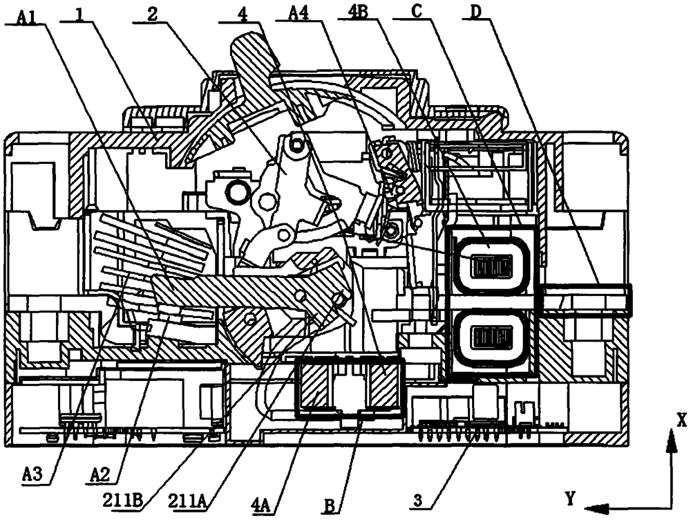
[0041] Such as figure 1, is a schematic diagram of a switch, the switch includes an insulating case 1, an operating mechanism 2, a moving contact A1, a static contact A2, an arc extinguishing chamber A3, a fault protection release A4, at least one electronic controller 3, at least one A current collector 4, the current load conductor passes through the current collector 4, the operating mechanism 2, the moving contact A1, the static contact A2, the arc extinguishing chamber A3, the fault protection release A4, the electronic controller 3 and The current collectors 4 are all arranged in the insulating casing 1 .

[0042] Such as figure 1 As shown, the current collector 4 includes a first current collector 4A and a second current collector 4B, and the first current collector 4A is arranged in the depth direction of the switch, that is, the X-axis direction shown in FIG. 1 The bottom or below of the operating mechanism 2 is as figure 1 The B area shown, that is: the first curr...

no. 2 example

[0060] Such as Figure 8 , is a schematic diagram of the second embodiment of the switch, the switch includes an insulating case 1, an operating mechanism 2, a moving contact A1, a static contact A2, an arc extinguishing chamber A3, a fault protection release A4, and at least one electronic controller 3 . At least one current collector 4 through which the current-carrying conductor passes.

[0061] The current collector includes at least one first current collector 4A and at least one second current collector 4B, and the first current collector 4A is along the depth direction of the switch, i.e. Figure 8 The X-axis direction shown is set at the bottom of the operating mechanism 2 as Figure 8 The B area shown, that is: the first current collector 3 is arranged on the side away from the handle of the operating mechanism 2 along the X-axis direction; at least one of the second current collectors 4B is along the depth of the switch Direction is Figure 8 The X-axis direction...

no. 3 example

[0064] Such as Figure 9 , is a schematic diagram of the third embodiment of a switch, the switch includes an insulating case 1, an operating mechanism 2, a moving contact A1, a static contact A2, an arc extinguishing chamber A3, a fault protection release A4, and at least one electronic controller 3 . At least one current collector 4 through which the current-carrying conductor passes. The current collector 4 includes at least one first current collector 4A and at least one second current collector 4B, and the first current collector 4A is along the depth direction of the switch, i.e. Figure 9 The X-axis direction shown is located at the bottom of the operating mechanism 2 as Figure 8Region B shown. The second current collector current collector 4B is along the depth direction of the switch, i.e. Figure 9 The X-axis direction shown is located on the bottom of the switch as Figure 9 Region C shown. In this example, the

[0065] Both the first current collector 4A an...


PUM


Abstract

The invention discloses a switch which comprises an insulating shell (1), an operating mechanism (2), a moving contact (A1), a static contact (A2), an arc extinguish chamber (A3), a fault protection tripper (A4), at least one electronic controller (3) and at least one current collector (4); a current load conductor penetrates through the current collector (4); and the switch is characterized in that the current collector (4) at least comprises a first current collector (4A), and the first current collector (4A) is arranged below a part from the operating mechanism (2) to a power outlet end D along the depth direction of the switch. The switch is reasonable in structural design, and the size of an original switch is not changed; and meanwhile, the switch is additionally provided with the functions of automatic physical topology support, in-situ fault study and judgment, HPLC communication, metering function, line loss analysis support and the like, so that the functions of the switch are expanded more.

Description

technical field [0001] The invention relates to the field of low-voltage electrical appliances, in particular to a switch with at least two sets of current collectors arranged in a phase / pole. Background technique [0002] As the State Grid continues to promote the ubiquitous power Internet of Things plan, various products in the power system continue to be upgraded and upgraded. In addition to maintaining the original functions of short circuit, undervoltage, leakage detection, and automatic closing and opening, the switch also adds line data detection, Remote communication, data display and other functions. In order to realize these new functions, it is necessary to add modules such as carrier and Bluetooth communication modules, electronic controllers, and data display modules to the switch. The addition of each module makes the internal space of the switch very crowded, especially when there are multiple sets of current collectors inside the switch. [0003] The problem...

Claims


Application Information

Patent Timeline
Patent Type & Authority Applications(China)
IPC IPC(8): H01H9/54
CPCH01H9/54
Inventor 南寅朱金保陈斌谷春雷连云飞于雷章龙施谦吕毅华张炎
Owner TIANJIN SVRUI INTELLIGENT ELECTRICAL CO LTD
Why Eureka
Try Eureka