Lamp power line fixing structure and implementation method thereof

A technology for fixing structures and power cords, applied in circuit layout, lighting devices, components of lighting devices, etc., can solve the problem that the wiring harness is easy to rotate and fall off, increase product thickness, operating procedures and material costs, and affect production efficiency and product safety. and other problems to achieve the effect of reducing cost increase and improving assembly efficiency

Pending Publication Date: 2021-10-01
HENGDIAN GRP TOSPO LIGHTING
View PDF0 Cites 0 Cited by
  • Summary
  • Abstract
  • Description
  • Claims
  • Application Information

AI Technical Summary

Problems solved by technology

[0004] (1), fixed with a wire buckle, increased product thickness, operating procedures and material costs;
[0005] (2) Fix it with glue, because the glue needs a certain period of time to solidify. Before the solidification is completed, the wire harness is easy to rotate and fall off during the transfer process, which affects production efficiency and product safety.

Method used


Image

  • Lamp power line fixing structure and implementation method thereof
  • Lamp power line fixing structure and implementation method thereof
  • Lamp power line fixing structure and implementation method thereof

Examples


Embodiment 1

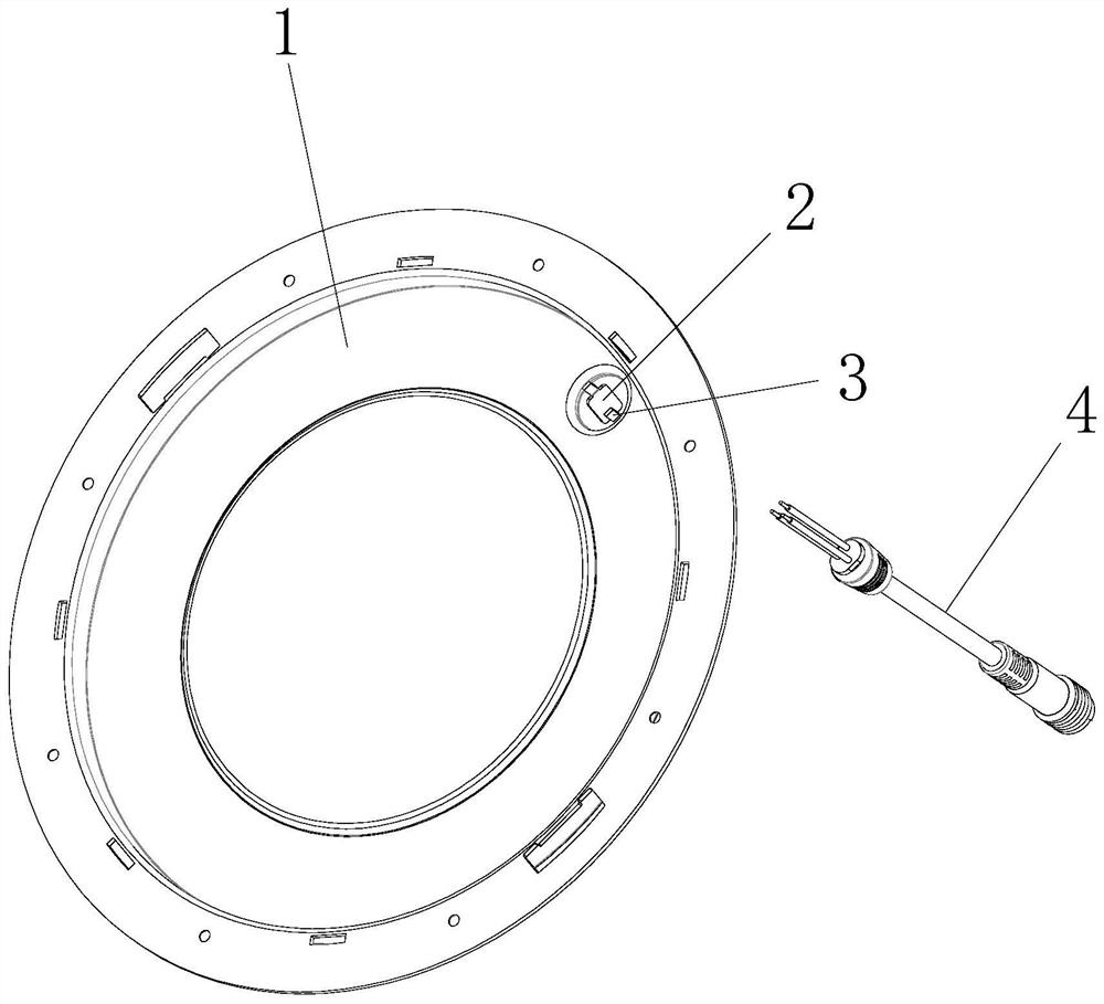
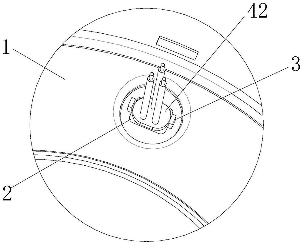
[0031] see Figure 1-5 , the present invention provides the following technical solutions: a lamp power cord fixing structure, including a metal shell 1 and a power cord body 4, the metal shell 1 is provided with a threading hole 2, the two sides of the threading hole 2 are provided with bending blocks 3, the power supply The circumference of the end of the wire body 4 is provided with a tail clip 42, and the tail clip 42 passes through the threading hole 2 and is fixed to the metal shell 1 by bending the bending block 3.

[0032] Specifically, the threading hole 2 is a rectangular structure, the bending blocks 3 are arranged on both sides of the short sides of the threading hole 2 , and the tail clip 42 is a rectangular structure with the same size as the threading hole 2 .

[0033] By adopting the above technical solution, after the tail clip 42 passes through the threading hole 2 and rotates 90 degrees, the threading hole 2 can limit the position of the tail clip 42 to prev...

Embodiment 2

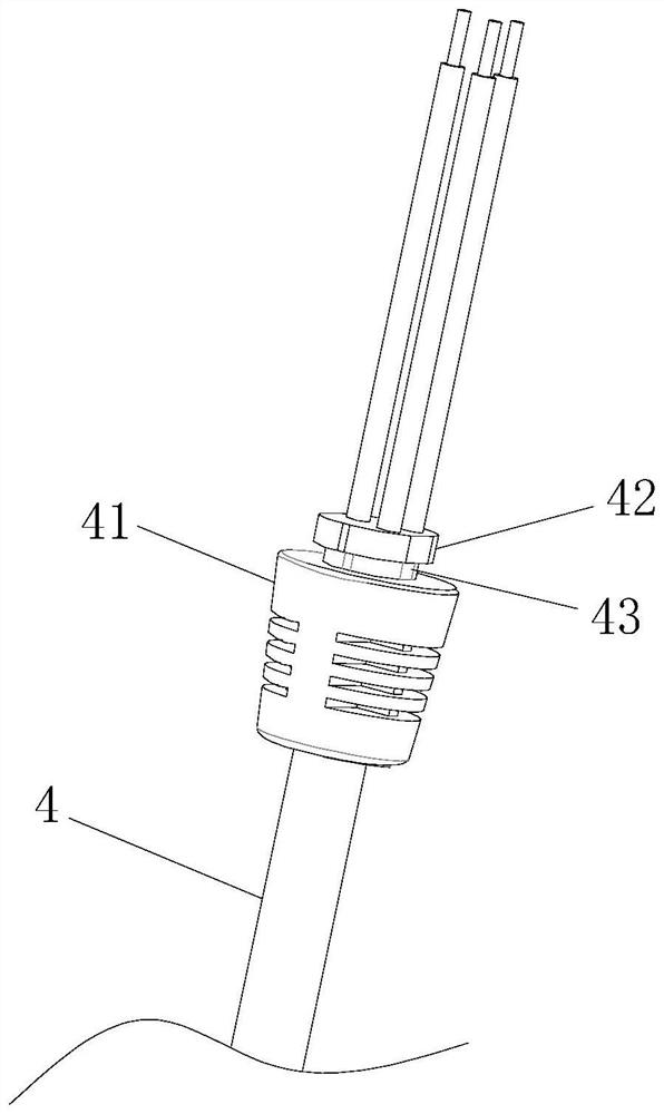
[0039] The difference between this embodiment and Embodiment 1 is that specifically, the circumference of the end of the power cord body 4 is also provided with a boss 41 located below the end card 42 and connected to the end card 42, and the boss 41 is a circular truncated structure , The diameter of the top surface of the boss 41 is larger than the length of the long side of the threading hole 2 .

[0040] By adopting the above technical solution, the power cord body 4 is limited by the boss 41 to prevent the power cord body 4 from being pushed in during installation or transportation. In addition, the boss 41 can restrain the wire hole 2 to a certain extent. Sealed so that it has a certain level of waterproofing.

[0041] Specifically, a rotating groove 43 is provided between the boss 41 and the tail clip 42 , and the width of the rotating groove 43 is greater than or equal to the thickness of the metal casing 1 .

[0042] By adopting the above technical solution, the tail...


PUM


Abstract

The invention discloses a lamp power line fixing structure. The lamp power line fixing structure comprises a metal shell and a power line body, a threading hole is formed in the metal shell, bending blocks are arranged on the two sides of the threading hole, a tail clamp is arranged on the circumference of the end of the power line body, and the tail clamp penetrates through the threading hole and then is fixed with the metal shell by bending the bending blocks. The invention further discloses an implementation method of the lamp power line fixing structure. According to the lamp power line fixing structure, the power line body and the metal shell can be fixed without using glue or a line buckle, so that the cost increase caused by pressing the line buckle or gluing is reduced, and the assembly efficiency and the product safety are improved at the same time; and the tail clamp passes through the threading hole and then is fixed with the metal shell by bending the bending blocks, so that the damage of outer skin of the power line body and the falling of a bonding pad caused by pulling, rotating and jacking the power line body in the installation or transportation process are avoided.

Description

technical field [0001] The invention belongs to the technical field of lamp power cord fixing, and in particular relates to a lamp power cord fixing structure and an implementation method thereof. Background technique [0002] The way to fix the power cord is different between the plastic shell and the metal shell. The plastic shell can use the characteristics of plastic deformation to snap on the power cord or other fastening methods to fix it, while the metal shell is not deformed enough to use the snap structure. [0003] The current conventional method is to fix the power cord with wire buckle or glue after the power cord passes through the threading hole of the metal shell, which has certain defects, such as: [0004] (1), fixed with a wire buckle, increased product thickness, operating procedures and material costs; [0005] (2) Fix it with glue, because the glue needs a certain period of time to solidify. Before the solidification is completed, the wire harness is ea...

Claims


Application Information

Patent Timeline
Patent Type & Authority Applications(China)
IPC IPC(8): F21V23/00
CPCF21V23/001
Inventor 李涛陈亮陈旭朱宇飞厉为民
Owner HENGDIAN GRP TOSPO LIGHTING
Why Eureka
Try Eureka