Method for processing catalytic converter for automobile

A processing method and catalyst technology, which are applied in the field of automobile post-treatment emission systems, can solve the problems of increasing gasket failure, carrier crushing, increasing manufacturing cost, etc., so as to reduce welding processes and necking processes, improve mechanical durability, reduce effect of cost increase

Inactive Publication Date: 2012-02-15
JAPHL POWERTRAIN SYST
View PDF6 Cites 6 Cited by
  • Summary
  • Abstract
  • Description
  • Claims
  • Application Information

AI Technical Summary

Problems solved by technology

[0002] The main body of the catalytic converter mainly includes a carrier, a liner, a shell, and a cone end. The traditional manufacturing process of a bundled catalytic converter is to first package the carrier, liner, and shell and then weld the end cone, which has complex processes and high costs. Defects, as follows:
[0003] Complex structure: In addition to the design of the carrier, liner, and shell parts, the bundled process also needs to design the end cone of the catalytic converter separately. In addition, in order to prevent the air flow from blowing the liner, the shrinkage design of the shell needs to be considered , and the installation and matching design of the end cone and the shell, resulting in a complex structure and a variety of design contents
[0004] There are many processes: the bundled catalytic converter needs to be stamped and formed except for the shell and the end cone. The assembly includes the bundled carrier, straight seam welding, circular seam welding and other processes, especially the uneven distribution of the gap at the edge of the shell. The shrinking process is very easy to cause the carrier to be broken, the process steps are numerous, and the investment in equipment is large
[0005] There are many welding parts: the bundled catalytic converter process needs to purchase the end cone separately, and the cost of parts procurement is high; the welding part includes two parts: straight seam welding and circular seam welding. The welding process of the body girth weld is prone to liner ablation, increasing the risk of liner failure and increasing the overall manufacturing cost

Method used


Image

  • Method for processing catalytic converter for automobile
  • Method for processing catalytic converter for automobile
  • Method for processing catalytic converter for automobile

Examples


Embodiment Construction

[0027] A method for processing a catalytic converter for automobiles, comprising:

[0028] 1) Roll the cylinder plate into the shape of the outer shell of the catalytic converter and round it;

[0029] 2) Fix the rolled cylinder body 1 by straight seam welding;

[0030] 3) Cut the two ends of the welded cylinder to the specified length, and remove the defective welds at the two ends;

[0031] 4) Wrap the liner 2 on the carrier 3 with adhesive tape, pay attention to the offset of the liner when it is pressed in;

[0032] 5) Press the wrapped carrier 3 into the barrel 1;

[0033] 6) Put the cylinder body 1 into the spinning jig for spinning;

[0034] 7) The thrust displacement test is carried out on the catalytic converter assembly after spinning.

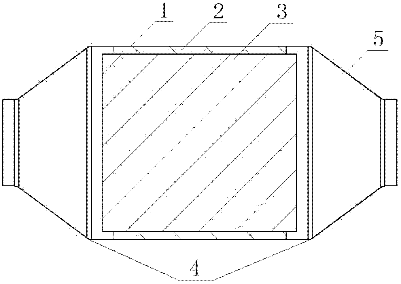
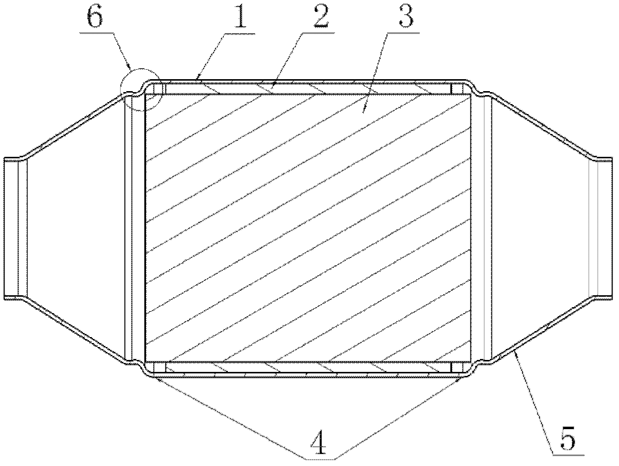
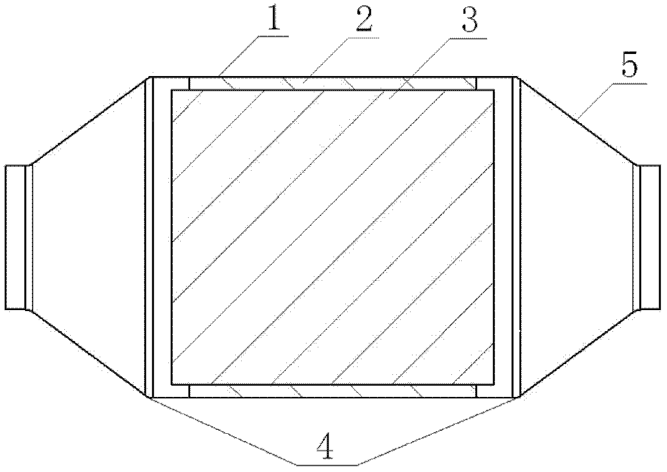
[0035] Wherein, the spinning in step 6) is to spin out the end cone 5 structure at both ends of the barrel 1 .

[0036] The schematic diagram of the structure of the catalytic converter processed by the above processing method i...


PUM


Abstract

The invention discloses a method for processing a catalytic converter for an automobile. The method comprises the following steps: 1) rolling a cylindrical plate sheet according to the shape of the shell of the catalytic converter and rounding; 2) fixing the rolled cylinder (1) in the manner of direct seam welding; 3) cutting two ends of the welded cylinder to appointed length, and meanwhile, removing welding joints with flaws from two ends; 4) wrapping a gasket (2) onto a carrier (3) by using an adhesive tape; 5) pressing the wrapped carrier (3) into the cylinder (1); 6) performing flow forming on the cylinder (1) by using a spinning fixture; and 7) performing a thrust displacement test on a formed catalytic converter assembly subjected to flow forming. The catalytic converter of the specific structure has the beneficial effects that flow forming end conical forming is performed on the two ends of the shell after the carrier and the gasket are pressed into the shell, thereby reducing the cost increase caused by end conical design and mould opening, omitting an end conical girth welding process and a necking down process in process aspect; and by the adoption of the catalytic converter, a compression gap of the gasket can be well ensured, the risk of carrier breaking is reduced, and mechanical durability of the catalytic converter is improved..

Description

technical field [0001] The invention relates to an automobile post-treatment exhaust system, in particular to a processing method for an integrally formed catalytic converter. Background technique [0002] The main body of the catalytic converter mainly includes a carrier, a liner, a shell, and a cone end. The traditional manufacturing process of a bundled catalytic converter is to first package the carrier, liner, and shell and then weld the end cone, which has complex processes and high costs. Defects, as follows: [0003] Complex structure: In addition to the design of the carrier, liner, and shell parts, the bundled process also needs to design the end cone of the catalytic converter separately. In addition, in order to prevent the air flow from blowing the liner, the shrinkage design of the shell needs to be considered , and the installation and matching design of the end cone and the shell, resulting in a complex structure and a variety of design contents. [0004] T...

Claims


Application Information

Patent Timeline
Patent Type & Authority Applications(China)
IPC IPC(8): B23P15/00
Inventor 许全瑞范礼李后良姜倩颜研
Owner JAPHL POWERTRAIN SYST
Why Eureka
Try Eureka