Coated article with IR reflecting layer and method of making same

a technology of ir reflecting layer and coating article, which is applied in the field of coating article with ir reflecting layer and making same, can solve the problems of needing further energy rating improvement, lack of conventional coated articles with respect to one or more, etc., and achieves low u-value, low emissivity, and low sheet resistance.

Inactive Publication Date: 2013-04-02
GUARDIAN EURO S A R L +1
View PDF50 Cites 15 Cited by
  • Summary
  • Abstract
  • Description
  • Claims
  • Application Information

AI Technical Summary

Benefits of technology

[0001]This application relates to a coated article including an infrared (IR) reflecting layer of a material such as silver or the like. In certain example embodiments, a layer comprising zinc oxide is provided under the IR reflecting layer in order to improve qualities thereof. In certain example embodiments, the coating is a single-silver type coating, and includes an overcoat including an uppermost layer of or including silicon nitride and a layer of or including tin oxide under the silicon nitride based layer. In certain example embodiments, the thicknesses of the silicon nitride based uppermost layer and the tin oxide based layer are balanced (e.g., substantially equal, or equal plus / minus about 10-15%). It has surprisingly been found that balancing the thicknesses of the silicon nitride based uppermost layer and the adjacent tin oxide based layer results in an overall coating that has significantly improved thermal cycling performance and improved mechanical durability. In certain example embodiments, the silicon nitride based uppermost layer and the tin oxide based layer of the overcoat each have a thickness of at least about 90 angstroms (Å), more preferably at least about 120 Å, and still more preferably at least about 150 Å. For example, the silicon nitride based uppermost layer and the tin oxide based layer may each be from about 160-180 Å thick in certain example embodiments, so as to improve thermal cycling performance and durability of the overall coating. In certain example embodiments, the coating also has surprisingly good substantially neutral film side reflective coloration, monolithically or more preferably in an insulating glass (IG) window unit.
[0002]In certain example embodiments, an IG window unit including the coating (e.g., on surface #3) has an SHGC value of no less than about 0.65, more preferably no less than about 0.68; and a visible transmission of at least about 68%, more preferably at least about 70%, 72%, or even at least about 74%. In certain example embodiments of this invention, the IG window unit can realize a combination of good visible transmission (Tvis) and an excellent solar heat gain coefficient (SHGC). In view of the above, it is possible to permit the coated article, such as an IG window unit for example, to realize improved properties such as one or more of a low U-value, and / or an Energy Rating (ER) of no less than 29. Additionally, in certain example embodiments, it has surprisingly been found that the stress of the overcoat can be unexpectedly reduced by reducing nitrogen gas flow (N2 ml / kW) and cathode power during the sputter-deposition process of the overcoat. It has been found that low overcoat stress is a factor contributing to good thermal cycling results.

Problems solved by technology

However, conventional coated articles are lacking with respect to one or more of: (i) thermal cycling performance, (ii) mechanical durability, (iii) ability to achieve good substantially neutral film side reflective coloration monolithically or more preferably in an insulating glass (IG) window unit, (iv) ability to realize a combination of good visible transmission (Tvis) and an excellent solar heat gain coefficient (SHGC) and low U-values for increasing or maximizing solar heat gain and reducing or minimizing heat loss of building interiors, and / or (v) ability to meet an Energy Rating (ER) of no less than 29.
In particular, they still need further energy rating improvement for residential applications in northern climates mainly due to not having a sufficiently high SHGC.

Method used


Image

  • Coated article with IR reflecting layer and method of making same
  • Coated article with IR reflecting layer and method of making same
  • Coated article with IR reflecting layer and method of making same

Examples


examples

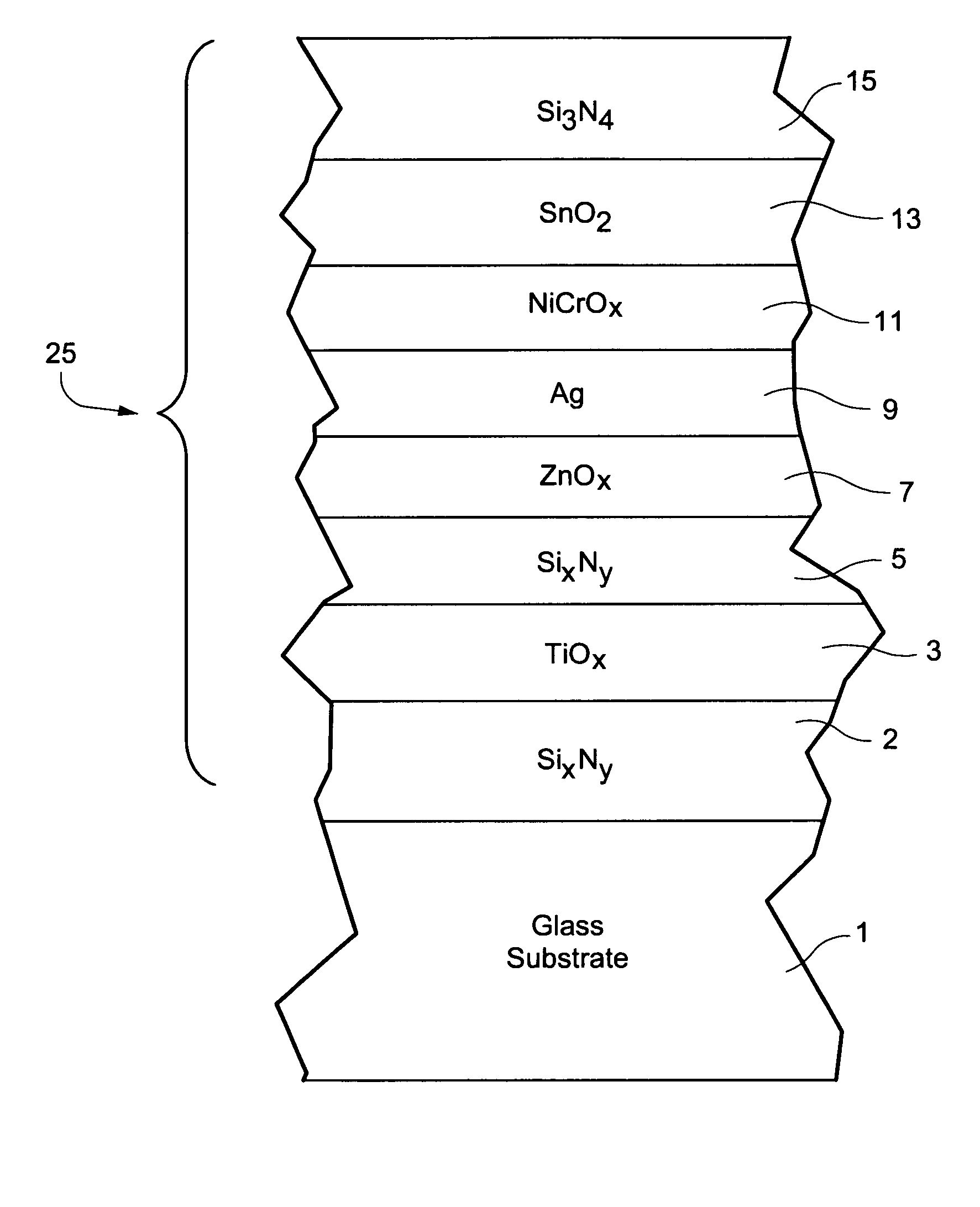
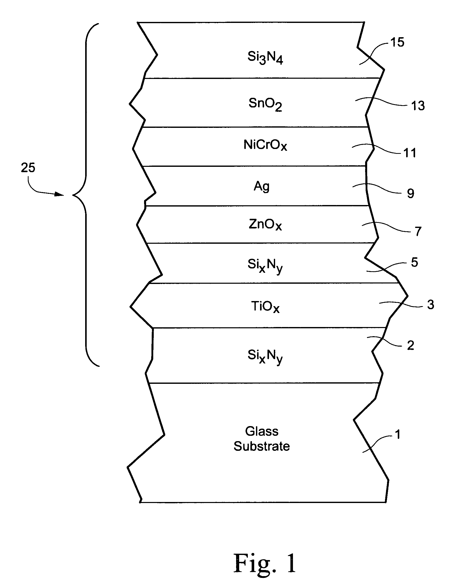
[0043]The following example is provided for purposes of example only, and is not intended to be limiting. The following Example 1 was made via sputtering so as to have approximately the layer stack set forth below, from the clear glass substrate outwardly. The listed thicknesses are approximations:

[0044]

TABLE 4Layer Stack for Example 1LayerThickness (angstroms)Glass Substrate3mmSi3N4135{acute over (Å)}TiOx95{acute over (Å)}Si3N465{acute over (Å)}ZnAlOx90{acute over (Å)}Ag85{acute over (Å)}NiCrOx30{acute over (Å)}SnO2170ÅSi3N4170{acute over (Å)}

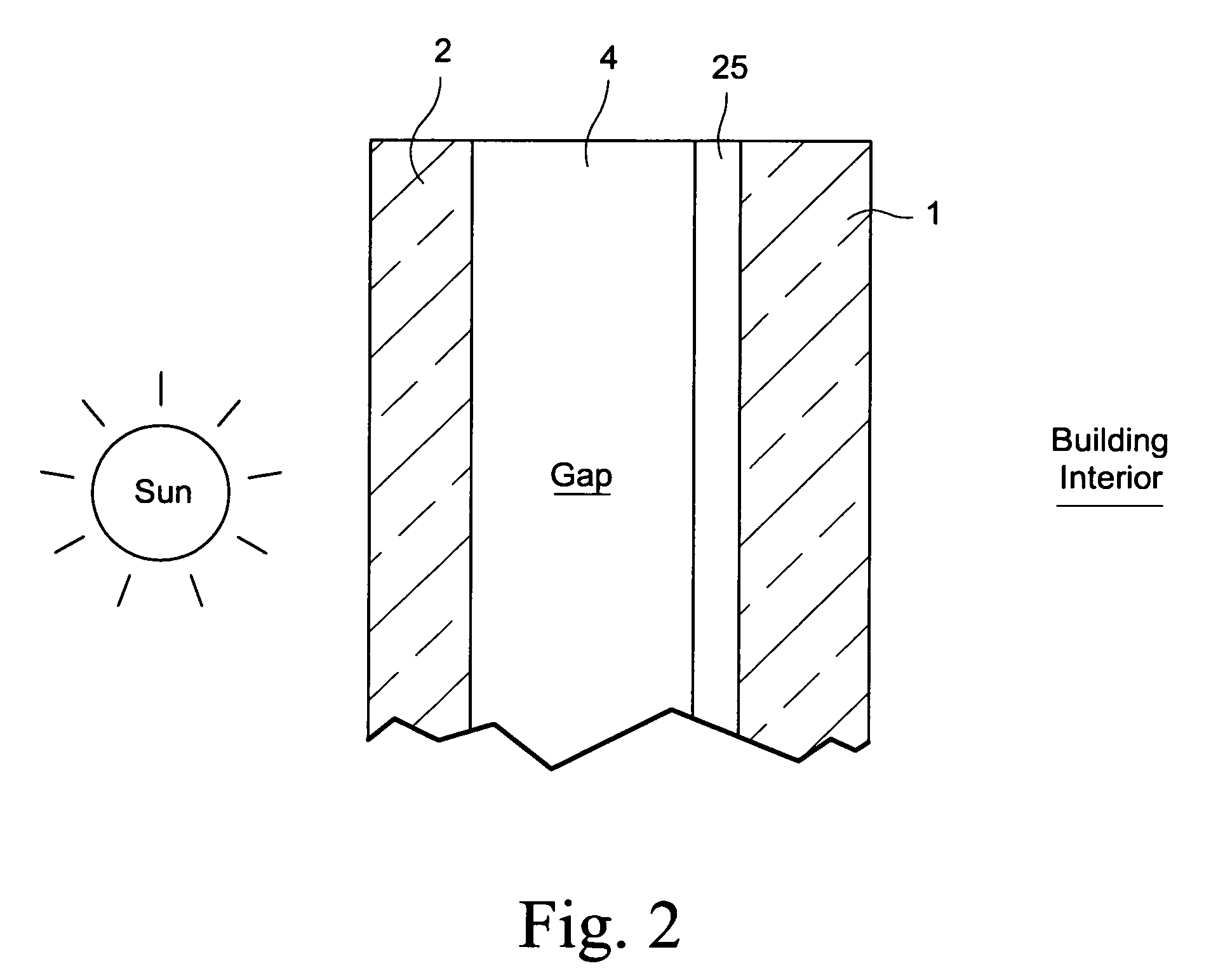
[0045]The two layers 13 and 15 of the overcoat were sputter-deposited to the same thickness. After being sputter deposited onto the glass substrate, the coated article of Example 1 (see also FIG. 1) was provided in an IG window unit as shown in FIG. 2 so that the coating 25 was on surface #3 of the IG unit. The characteristics of Example 1 are shown in FIG. 3.

[0046]Example 2 was the same as Example 1, except that layer 5 was not present in Exa...


PUM

PropertyMeasurementUnit
sheet resistanceaaaaaaaaaa
SHGCaaaaaaaaaa

Abstract

Example embodiments of this invention relate to a coated article including an infrared (IR) reflecting layer of a material such as silver or the like, for use in an insulating glass (IG) window unit for example. In certain example embodiments, the coating is a single-silver type coating, and includes an overcoat including an uppermost layer of or including silicon nitride and a layer of or including tin oxide immediately under and contacting the silicon nitride based overcoat. In certain example embodiments, the thicknesses of the silicon nitride based overcoat and the tin oxide based layer are balanced (e.g., substantially equal, or equal plus / minus about 10%). It has surprisingly been found that such balancing results in an improvement in thermal cycling performance and improved mechanical durability. In certain example embodiments, the coating may realize surprisingly good substantially neutral film side reflective coloration, and may achieve an improved visible transmission, SHGC ratio and low U-values. Moreover, in certain example embodiments, stress in the overcoat of the coating may be reduced by reducing nitrogen gas flow (N2 ml / kW) and cathode power during a sputter-deposition process, thereby further improving thermal cycling performance.

Description

[0001]This application relates to a coated article including an infrared (IR) reflecting layer of a material such as silver or the like. In certain example embodiments, a layer comprising zinc oxide is provided under the IR reflecting layer in order to improve qualities thereof. In certain example embodiments, the coating is a single-silver type coating, and includes an overcoat including an uppermost layer of or including silicon nitride and a layer of or including tin oxide under the silicon nitride based layer. In certain example embodiments, the thicknesses of the silicon nitride based uppermost layer and the tin oxide based layer are balanced (e.g., substantially equal, or equal plus / minus about 10-15%). It has surprisingly been found that balancing the thicknesses of the silicon nitride based uppermost layer and the adjacent tin oxide based layer results in an overall coating that has significantly improved thermal cycling performance and improved mechanical durability. In cer...

Claims


Application Information

Patent Timeline
Patent Type & Authority Patents(United States)
IPC IPC(8): B32B17/06B32B15/04
CPCC03C17/36C03C17/3626C03C17/3634C03C17/3644C03C17/3652C03C17/366C03C17/3681B32B17/06E06B3/6715C03C17/3618Y10T428/265C03C2217/21C03C2217/256C03C2217/219C03C2217/216C03C2217/212C03C2217/281C03C2218/154C03C2218/156B32B2255/20B32B2255/28B32B2307/304B32B2307/412B32B2307/416C03C17/2453C03C17/3435C03C2217/211C03C2217/70C23C14/0652C23C14/086E06B9/24E06B2009/2417
Inventor LAO, JINGYULINGLE, PHILIP J.BOYCE, BRENTDISTELDORF, BERNDBLACKER, RICHARD
Owner GUARDIAN EURO S A R L
Why Eureka
Try Eureka