
Rotor mechanism and rotary vane engine

A technology of engines and rotors, which is applied in the direction of machines/engines, combustion engines, internal combustion piston engines, etc., and can solve problems such as inconvenient use, affecting the sealing of the chamber separated by the leaves, and affecting the service life of the engine.

Pending Publication Date: 2021-10-08
李炳强
View PDF0 Cites 0 Cited by
  • Summary
  • Abstract
  • Description
  • Claims
  • Application Information

AI Technical Summary

Problems solved by technology

[0002] Among the existing engines, the engines with relatively mature technology are mainly reciprocating piston engines and rotary engines. For rotary engines, the abutment between the blades on the rotor and the inner wall of the casing is generally through the blades themselves. The rotational inertia of the leaf itself or the elastic force of the spring is used to abut against the inner wall of the casing through the rotational inertia of the leaf itself, the effectiveness of the abutment is poor, and abutment failure is prone to occur. Affect the sealing of the chamber separated by the leaf; for the method of abutting the leaf and the inner cavity wall of the casing through the elastic force of the spring, due to the spring has a certain service life, it may occur after a long period of use. Elastic failure will affect the service life of the engine. At the same time, it is easy to cause a gap between the blade and the inner wall of the casing, which will affect the sealing of the chamber separated by the blade. Regular maintenance is required, and the setting of the elastic member will cause the rotor mechanism to The connection structure is more complicated, the assembly and disassembly are more troublesome, and it is not easy to use

Method used


Image

  • Rotor mechanism and rotary vane engine
  • Rotor mechanism and rotary vane engine
  • Rotor mechanism and rotary vane engine

Examples


Embodiment Construction

[0042] Embodiments of the present invention are described in detail below, examples of which are shown in the drawings, wherein the same or similar reference numerals designate the same or similar elements or elements having the same or similar functions throughout. The embodiments described below by referring to the figures are exemplary only for explaining the present invention and should not be construed as limiting the present invention.

[0043] In the description of the present invention, it should be understood that if it involves orientation descriptions, for example, the orientation or positional relationship indicated by up, down, left, right, etc. is based on the orientation or positional relationship shown in the drawings, and is only for the convenience of description The present invention and simplified description do not indicate or imply that the device or element referred to must have a specific orientation, be constructed and operate in a specific orientation,...


PUM


Abstract

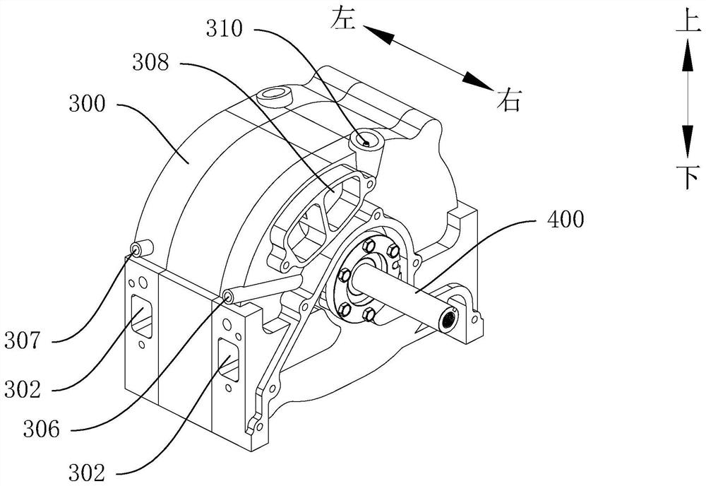
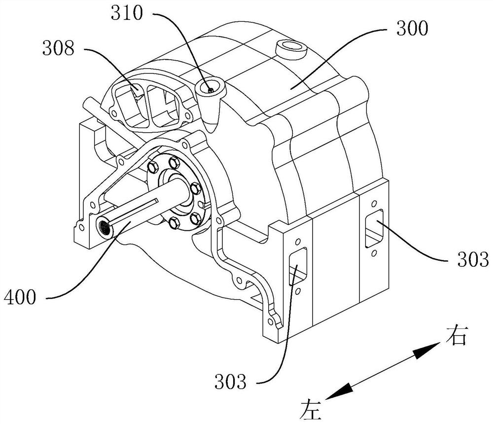
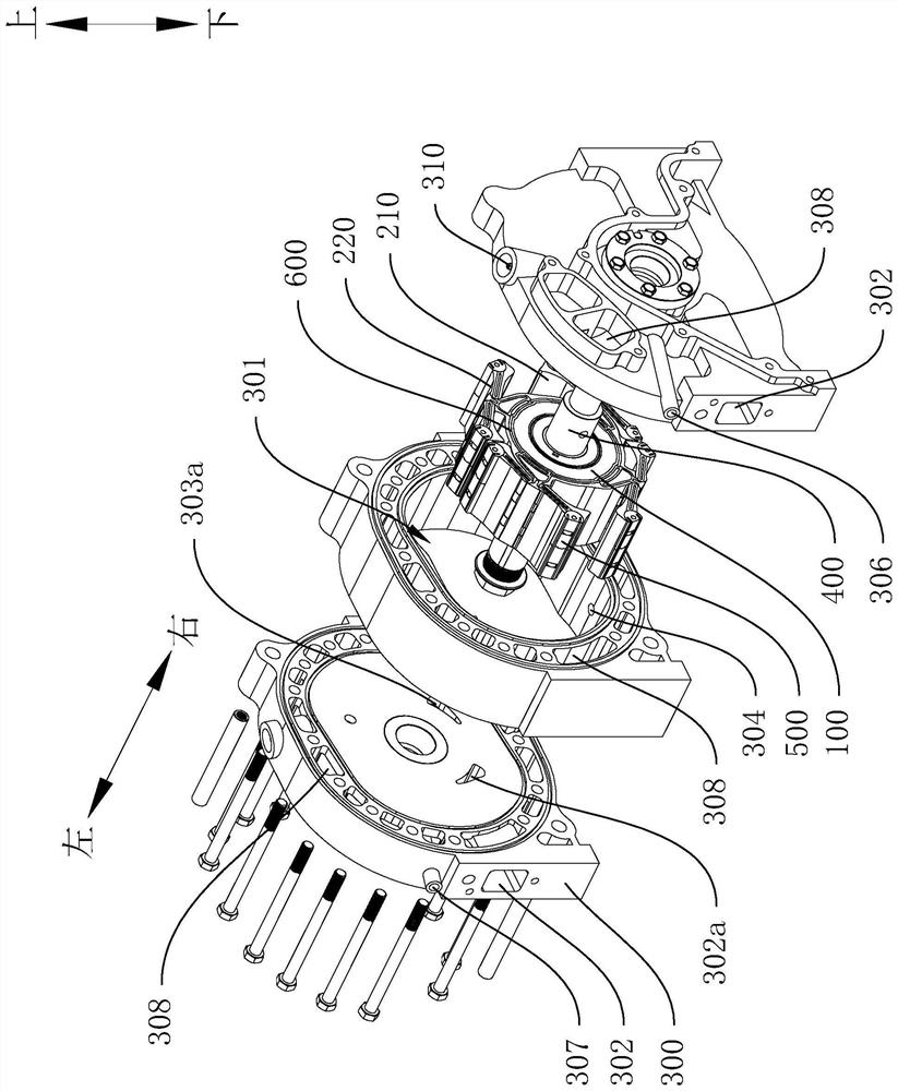
The invention discloses a rotor mechanism and a rotary vane engine. The rotary vane engine comprises a machine shell assembly, a rotating shaft part and the rotor mechanism, the rotor mechanism comprises a rotor seat and at least one set of vane group, a first channel is arranged on the rotor seat, each set of vane group comprises a first vane and a second vane which are rotatably connected to the rotor seat, the machine shell assembly is provided with a machine shell inner cavity, a first input channel and a first output channel, the rotor mechanism is located in the machine shell inner cavity and connected with the rotating shaft part, the first vane and the second vane can rotate to abut against the wall face of the machine shell inner cavity under the action of fluid pressure in the first channel so that a combustion cavity can be separated in the machine shell inner cavity, the combustion cavity can drive the rotor mechanism to rotate through combustion expansion of fuel so as to have different states, and the first input channel and the first output channel can communicate with the combustion cavities in the different states correspondingly. According to the rotor mechanism and the rotary vane engine, by means of the pressure of fluid, abutting of the vanes can be stable and reliable, and the use reliability is improved.

Description

technical field [0001] The invention relates to the technical field of engines, in particular to a rotor mechanism and a vane engine. Background technique [0002] Among the existing engines, the engines with relatively mature technology are mainly reciprocating piston engines and rotary engines. For rotary engines, the abutment between the blades on the rotor and the inner wall of the casing is generally through the blades themselves. The rotational inertia of the leaf itself or the elastic force of the spring is used to abut against the inner wall of the casing through the rotational inertia of the leaf itself, the effectiveness of the abutment is poor, and abutment failure is prone to occur. Affect the sealing of the chamber separated by the leaf; for the method of abutting the leaf and the inner cavity wall of the casing through the elastic force of the spring, due to the spring has a certain service life, it may occur after a long period of use. Elastic failure will af...

Claims


Application Information

Patent Timeline
IPC IPC(8): F02B55/02F02B55/04F02B55/00F02B53/02F02B53/04
CPCF02B55/02F02B55/04F02B55/00F02B53/02F02B53/04Y02T10/12
Inventor 李炳强
Owner 李炳强
Learn More