Safety switch for electric heater and electric heater

A technology for safety switches and electric heaters, applied in applications, electric heating systems, household heating, etc., can solve problems such as burning out electric heaters, hindering heat dissipation of electric heaters, and clothing fires, and achieves the effect of improving practicability

Active Publication Date: 2022-08-09
慈溪市新秀丽电器有限公司
View PDF0 Cites 0 Cited by
  • Summary
  • Abstract
  • Description
  • Claims
  • Application Information

AI Technical Summary

Problems solved by technology

[0004] The present invention solves the problem that in the process of drying clothes, when the clothes fall on the electric heater, it will hinder the heat dissipation of the electric heater, burn out the electric heater or ignite the clothes and cause a fire. Safety switches for heaters and electric heaters

Method used


Image

  • Safety switch for electric heater and electric heater
  • Safety switch for electric heater and electric heater
  • Safety switch for electric heater and electric heater

Examples


Embodiment approach

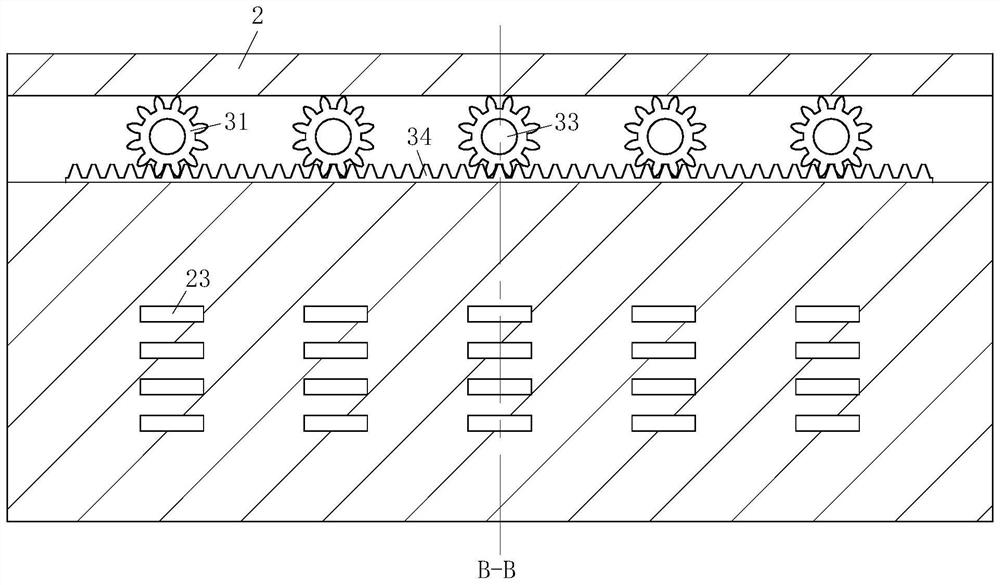
[0042] As a specific embodiment of the present invention, the heat dissipation module 3 includes a gear 31 , a plurality of fins 32 and a plurality of connecting shafts 33 . The connecting shafts 33 are rotatably connected to the U-shaped accommodating box 2 , and the connecting shafts 33 A gear 31 is fixed at one end of the radiator, the gear 31 is engaged with a rack 34, the rack 34 slides in the side wall of the U-shaped accommodating box 2, and a plurality of the heat dissipation modules 3 are meshed and connected by the gear 31 and the rack 34, The other end of the connecting shaft 33 is fixedly connected to the swing mechanism 4 through the fins 32 and the side wall of the U-shaped accommodating box 2 .

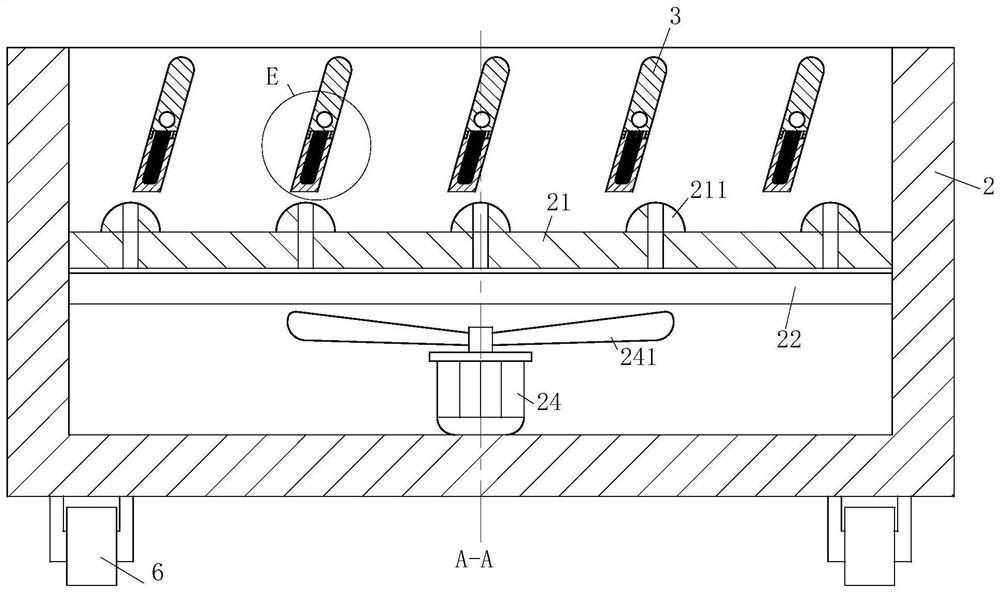
[0043] The present invention drives the connecting shaft 33 to rotate through the swing mechanism 4, and then drives the fins 32 to rotate, and cooperates with the wind power output by the No. 1 motor 24 to achieve the purpose of conveying the heat of the heating pipe 22...

specific Embodiment approach

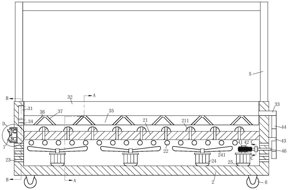
[0050] As a specific embodiment of the present invention, a plurality of protrusions 211 are provided on the side of the partition plate 21 close to the upper chamber, and through holes are provided in the protrusions 211, and the through holes connect the upper chamber to the upper chamber. The lower chamber is connected, and the present invention uses a plurality of protrusions 211 to prevent water from entering the lower chamber through the through hole when water is artificially added.

[0051]Working principle: In the present invention, the clothes drying rack 5 is artificially fixed on the top of the electric heater, the clothes to be dried are hung on the clothes drying rack 5, and then the switch is turned on to make the heating pipe 22, the No. 1 motor 24 and the No. 2 motor 25. When the power is connected, the No. 2 motor 25 drives the worm 42 engaged with the worm wheel 41 to rotate, and then drives the connecting rod 46 to rotate through the ratchet and the paddle 4...


PUM


Abstract

The invention relates to the technical field of heating equipment, in particular to a safety switch for an electric heater and an electric heater. A safety switch for an electric heater comprises a U-shaped casing, and a pressing block is rotatably connected in the U-shaped casing, so that the A coil and a touch switch are fixed on the bottom end inside the U-shaped shell. An electric heater includes the above-mentioned safety switch and a U-shaped accommodating box, wherein a heat dissipation module is rotatably connected in the U-shaped accommodating box, and a swing mechanism is arranged in the U-shaped accommodating box, and the swing mechanism is connected to the U-shaped accommodating box. The heat dissipation module is fixedly connected; the top of the U-shaped accommodating box is fixed with a clothes drying rack. The invention uses the electric heater to dry the clothes on the drying rack, and when the drying rack is removed, it can also provide heat for people in winter; through the heat dissipation module, on the one hand, it cooperates with the safety switch to prevent the clothes on the drying rack from being heated by the electric heater. On the other hand, it cooperates with the swing mechanism to guide the heat dissipation direction and better dry the clothes on the drying rack.

Description

technical field [0001] The invention relates to the technical field of heating equipment, in particular to a safety switch for an electric heater and an electric heater. Background technique [0002] In daily life, due to climatic reasons, it is difficult to dry clothes, which brings inconvenience to users. Especially in winter or the rainy season, the air humidity is high, and the washed clothes are not easy to dry in the natural drying condition. In order to solve the problem that the clothes are difficult to dry due to climate reasons, people use a clothes drying rack on the heater to dry the clothes around the heater, so that the clothes are easier to dry, but in the process of drying the clothes, When clothes fall on the heater, it will hinder the heat dissipation of the heater, burn out the heater or ignite the clothes and cause a fire; [0003] Therefore, the present invention provides a safety switch for an electric heater and an electric heater. SUMMARY OF THE I...

Claims


Application Information

Patent Timeline
Patent Type & Authority Patents(China)
IPC IPC(8): F24D19/10F24D13/00D06F57/12
CPCF24D19/1096F24D13/00D06F57/12F24D2200/08Y02B30/00
Inventor 何胜阳张亮亮
Owner 慈溪市新秀丽电器有限公司
Why Eureka
Try Eureka