
Heat treatment processing device for bearing ring processing

A technology for bearing rings and processing devices, applied in heat treatment furnaces, heat treatment equipment, heat treatment process control, etc., can solve problems such as reducing work efficiency, increasing overall working time, and quenching devices that cannot perform continuous and continuous quenching treatment. Achieve the effect of improving quenching efficiency and speed and avoiding overall work efficiency

Active Publication Date: 2021-10-15
浙江赛赛轴承有限公司
View PDF3 Cites 2 Cited by
  • Summary
  • Abstract
  • Description
  • Claims
  • Application Information

AI Technical Summary

Problems solved by technology

[0003] The object of the present invention is to address the shortcomings of the prior art, to provide a heat treatment processing device for bearing ring processing, to solve the problem that the existing heater proposed in the above background technology is only installed on one heating wire for quenching treatment, This not only reduces the overall efficiency but also increases the overall working time. At the same time, the existing quenching device places the quenching parts directly under the heating wire for quenching treatment, which not only results in a long heating time for the overall quenching parts but also causes uneven heating of the quenching parts. In turn, the existing quenching device cannot perform continuous and continuous quenching treatment, which in turn reduces the overall work efficiency

Method used


Image

  • Heat treatment processing device for bearing ring processing
  • Heat treatment processing device for bearing ring processing
  • Heat treatment processing device for bearing ring processing

Examples


Embodiment Construction

[0031] The following will clearly and completely describe the technical solutions in the embodiments of the present invention with reference to the accompanying drawings in the embodiments of the present invention. Obviously, the described embodiments are only some, not all, embodiments of the present invention. Based on the embodiments of the present invention, all other embodiments obtained by persons of ordinary skill in the art without making creative efforts belong to the protection scope of the present invention.

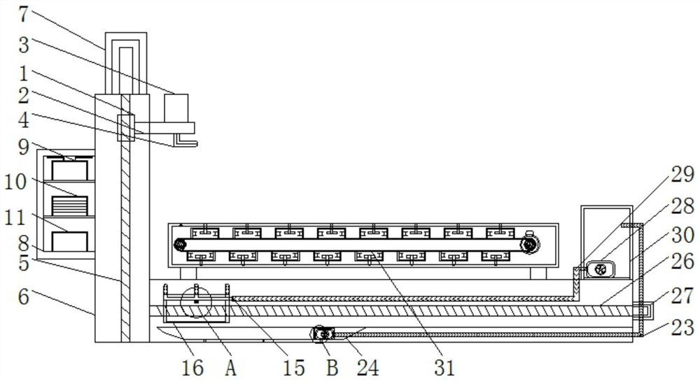
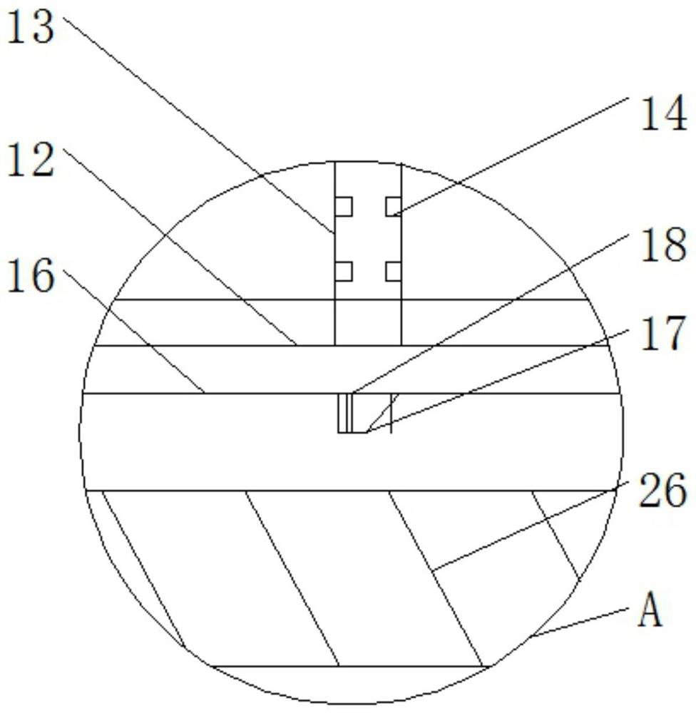
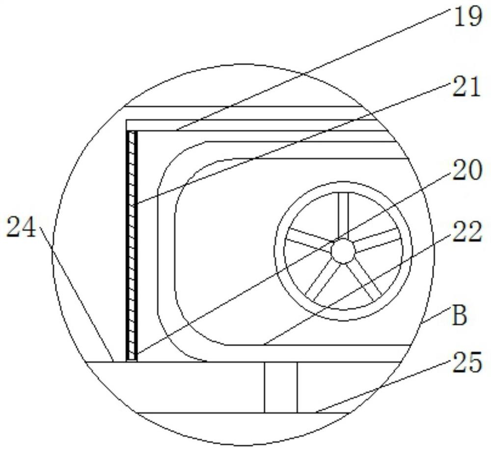
[0032] see Figure 1-8 , the present invention provides a technical solution: a heat treatment processing device for bearing ring processing, such as figure 1 , figure 2 , image 3 and Figure 4 As shown, the connecting plate 2 is fixed on the right side of the first wire block 1, and the heater 3 is fixed on the top of the connecting plate 2 through a hexagonal bolt. 2, and the heating wire 4 is arranged symmetrically with respect to the center line on t...


PUM


Abstract

The invention discloses a heat treatment processing device for bearing ring processing. The device comprises a first screw block, a heating wire, a first screw rod, a control box, a hollowed plate, a second screw block, a second mounting frame, a water suction pump, a second screw rod, a water pump and a conveying quenching device, the right side of the first screw block is fixedly connected to a connecting plate, the top end of the heating wire penetrates through the connecting plate to be fixedly connected to the bottom of a heater, the bottom of the first screw rod penetrates through the outer wall of the top end of the first mounting frame and the first screw block to extend into the first mounting frame, a signal receiver is mounted on the upper portion inside the control box through a partition plate, and a control panel is mounted under the signal receiver. According to the heat treatment processing device for bearing ring processing, heating wires are arranged, two bearing rings are quenched at the same time through the arrangement of the two heating wires, and therefore the situation that the quenching speed of the whole bearing rings is affected and the whole quenching efficiency is also affected due to the fact that the bearing rings are heated and quenched by a single heating wire is avoided.

Description

technical field [0001] The invention relates to the technical field of bearing ring processing, in particular to a heat treatment processing device for bearing ring processing. Background technique [0002] Bearings are one of the connecting parts for connection and transmission between parts, and the bearings are divided into connecting parts assembled and combined with bearing rings, balls, mounting frames and inner shafts, and the bearing rings are installed in the connecting holes Internally, the overall hardness of the bearing ring is the key to manufacturing the bearing ring, but the existing bearing ring needs to be quenched after being processed by a lathe, but the existing quenching device heats the heating wire through a heater, so that The bearing ring is heated and quenched through the heating wire, but the existing heater is only installed on one heating wire for quenching, which not only reduces the overall efficiency but also increases the overall working time...

Claims


Application Information

Patent Timeline
Patent Type & Authority Applications(China)
IPC IPC(8): C21D9/40C21D1/62C21D11/00
CPCC21D9/40C21D1/62C21D11/00Y02P10/25
Inventor 毛永成
Owner 浙江赛赛轴承有限公司
Learn More