
Laser system probe structure

A laser system and probe technology, which is applied to measurement devices, optical devices, instruments, etc., can solve the problems of low measurement accuracy, inability to measure, and low part measurement efficiency, and achieve high measurement accuracy, improved accuracy and flexibility. , a wide range of effects

Pending Publication Date: 2021-10-15
杭州垦驱智能科技有限公司
View PDF0 Cites 0 Cited by
  • Summary
  • Abstract
  • Description
  • Claims
  • Application Information

AI Technical Summary

Problems solved by technology

[0002] In the field of traditional parts processing, after the parts are processed, it is necessary to test the geometric dimensions and shape and position tolerances of the parts to achieve the qualified part parameters. When geometrical features are measured with a laser system, it is usually difficult to achieve due to the limitation of the feature structure of the workpiece, resulting in low efficiency of part measurement, low measurement accuracy, or even impossible measurement

Method used


Image

  • Laser system probe structure
  • Laser system probe structure
  • Laser system probe structure

Examples


Embodiment Construction

[0025] The following will clearly and completely describe the technical solutions in the embodiments of the present invention with reference to the accompanying drawings in the embodiments of the present invention. Obviously, the described embodiments are only some, not all, embodiments of the present invention. Based on the embodiments of the present invention, all other embodiments obtained by persons of ordinary skill in the art without making creative efforts belong to the protection scope of the present invention.

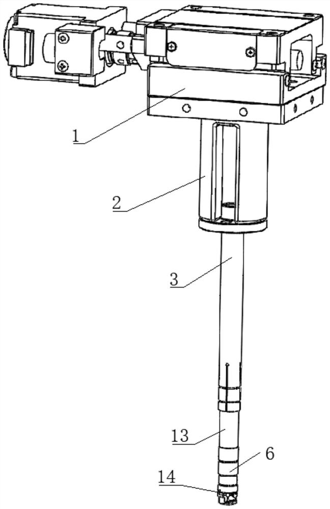
[0026] see figure 1 , the present invention provides a technical solution: a laser system measuring head structure, including a single-axis moving mechanism 1, a connecting piece 2, a sensor elastic fixing bracket, a laser sensor 13 and a quick-change laser reflection mechanism 14,

[0027] The elastic fixing bracket of the sensor is connected with the running end of the single-axis moving mechanism 1 through the connecting piece 2,

[0028] The laser sensor ...


PUM


Abstract

The invention relates to the technical field of detection probes, in particular to a laser system probe structure which comprises a single-axis moving mechanism, a connecting piece, a sensor elastic fixing support, a laser sensor and a quick-change laser reflecting mechanism. The sensor elastic fixing support is connected with the operating end of the single-axis moving mechanism through the connecting piece, the laser sensor is arranged at the elastic clamping end of the sensor elastic fixing support, and the quick-change laser reflection mechanism is installed at the detection end of the laser sensor. The measuring accuracy and the application range of the probe can be improved.

Description

technical field [0001] The invention relates to the technical field of detection probes, and the specific field is a laser system probe structure. Background technique [0002] In the field of traditional parts processing, after the parts are processed, it is necessary to test the geometric dimensions and shape and position tolerances of the parts to achieve the qualified part parameters. When geometrical features are measured with a laser system, it is usually difficult to realize due to the limitation of the feature structure of the workpiece, resulting in low efficiency of part measurement, low measurement accuracy, or even impossible measurement. Contents of the invention [0003] In view of the deficiencies in the prior art, the purpose of the present invention is to provide a laser system measuring head structure. [0004] In order to achieve the above object, the present invention provides the following technical solutions: a laser system measuring head structure, ...

Claims


Application Information

Patent Timeline
IPC IPC(8): G01B11/00
CPCG01B11/00
Inventor 黄文广张耀
Owner 杭州垦驱智能科技有限公司
Learn More