Circuitry and method for measuring time interval with ring oscillator

a technology of ring oscillator and time interval, which is applied in the direction of distance measurement, instruments, and using reradiation, can solve the problems of increasing the amount of propagation delay units, limiting the expandability and measuring range, and providing high precision of tdc, so as to simplify calibration procedures and simplify circuitry. the effect of complex circuitry

Active Publication Date: 2005-11-24
NAT CHUNG SHAN INST SCI & TECH
View PDF2 Cites 24 Cited by
  • Summary
  • Abstract
  • Description
  • Claims
  • Application Information

AI Technical Summary

Benefits of technology

[0023] According to the above descriptions, a ring oscillator module is provided in the present invention using propagation delay time of the delay devices (e.g. NAND gate and inverters) as reference of measuring precision. Therefore, only the parameters of the IC manufacturing process of the inverting devices, an amount of devices and stages of the counter are subjected to change measuring precision and range, where complexity of the circuitry is not increased. Ad

Problems solved by technology

This propagation delay TDC provides high precision (tens of ps), yet is limited in expandability and measuring range.
If to increase measuring range, an amount of propagation delay units is inc

Method used


Image

  • Circuitry and method for measuring time interval with ring oscillator
  • Circuitry and method for measuring time interval with ring oscillator
  • Circuitry and method for measuring time interval with ring oscillator

Examples


Embodiment Construction

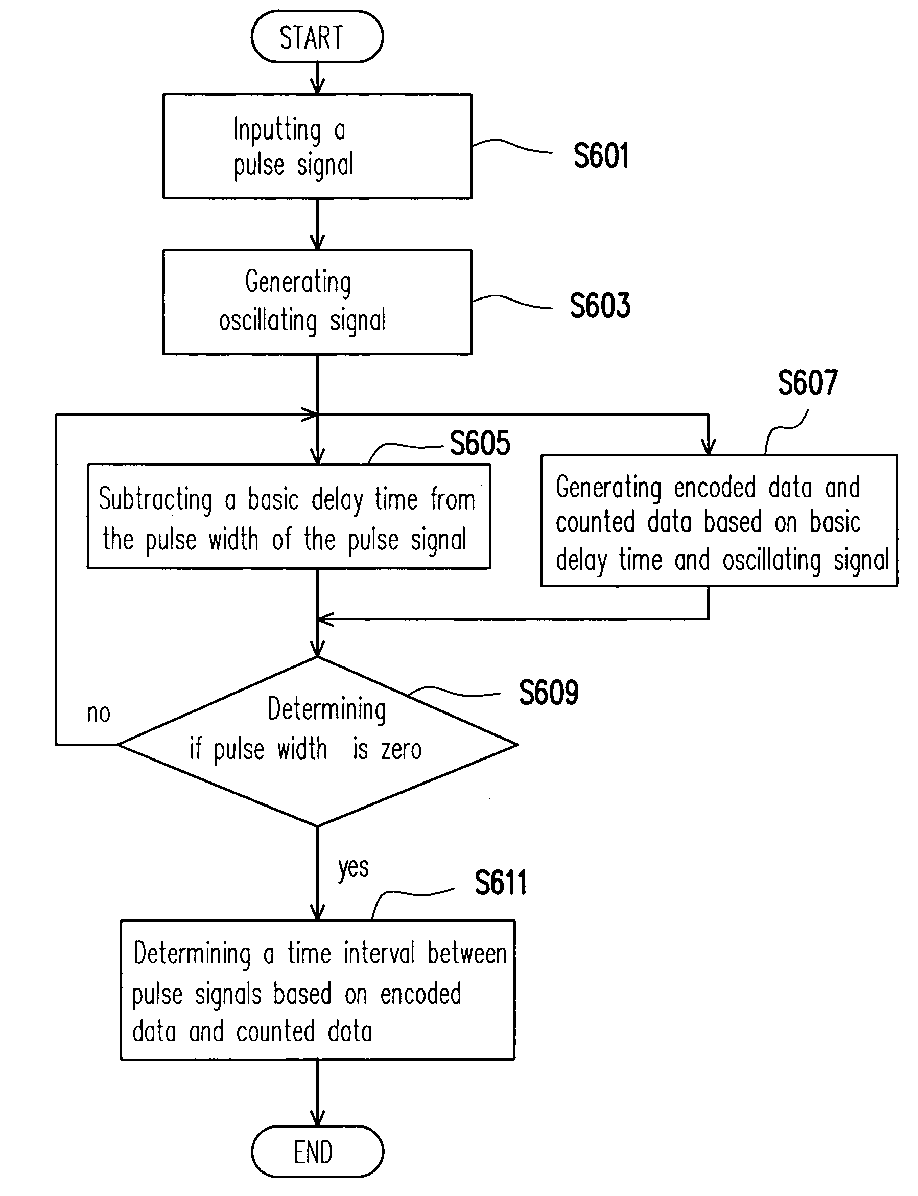
[0035] Referring to FIG. 4, it illustrates a block diagram of a circuit for measuring the time interval using ring oscillator scheme. In FIG. 4, the ring oscillator module 410 is activated by the input pulse signal Vin, and generating a plurality of oscillating signals to the encoder 420, so as to generate a plurality of encoded signals by encoding the oscillating signals from the ring oscillator module 410. Moreover, the counter 430 receives oscillating signals generated by the ring oscillator module 410, and generates the counting value based on one of the oscillating signals. When the pulse signal Vin becomes zero, a time interval Tin corresponding to the pulse width of the pulse signal Vin is obtained based on the encoded signal and the counting value.

[0036] Referring to FIG. 5A, it illustrates the internal logic circuit of the ring oscillator module according to one embodiment of the present invention. In FIG. 5A, the ring oscillator module comprises a plurality of delay switc...


PUM


Abstract

A circuitry for measuring a time interval with ring oscillator has a ring oscillator formed by a plurality of delay switching units, a counter and an encoder. Wherein, the ring oscillator generates a plurality of oscillating signals when receives a pulse signal used to turn on or turn off the ring oscillator. The counter can count the numbers of the oscillating signal during an active period of the pulse signal to generate a counting value. In addition, the encoder encodes the oscillation signals generated by a plurality of delay switching unit with a certain interval of delay time. Therefore, when the pulse signal is disabled to lead to turn off the ring oscillator, one can obtain the time interval of the pulse signal based on the encode data and the counting value.

Description

BACKGROUND OF THE INVENTION [0001] 1. Field of Invention [0002] The present invention relates to a circuit for measuring time interval, and more particularly, to a circuit for measuring a time interval using ring oscillator scheme. [0003] 2. Description of the Related Art [0004] In signal processing field, a time interval corresponding to the pulse width of a pulse signal, or a time interval between two digital pulse edges is usually needed. For example, when measuring distance with laser, calculating a time interval between the start digital signal when emitting laser pulse and the stop digital signal when receiving the reflected laser signal from the object, and multiplying with light speed, a distance between the origin and the object is obtained. Generally speaking, the time interval described above is substantially short, usually measured in the order of nanosecond (ns). Therefore, it is desired to measure a time interval with high precision. [0005] Referring to FIG. 1, it illu...

Claims


Application Information

Patent Timeline
IPC IPC(8): G01C3/08G01S7/285G01S15/00G06F9/45G06F17/50
CPCG01S7/285G04F10/005
Inventor LIN, YEAH-MINLUO, KUANG-TSOCHEN, REN-HERWU, SAU-MOULIN, YUN-HSIENWANG, TSUN-HSIN
Owner NAT CHUNG SHAN INST SCI & TECH
Why Eureka
Try Eureka