A robot joint acceleration constraint planning method and system

A robot joint and acceleration technology, which is applied in the direction of manipulators, program-controlled manipulators, manufacturing tools, etc., can solve the problem that the acceleration and deceleration capabilities of the motor shaft are not fully utilized, and achieve the effect of improving motion efficiency

Active Publication Date: 2022-05-17
HUAZHONG UNIV OF SCI & TECH
View PDF5 Cites 0 Cited by
  • Summary
  • Abstract
  • Description
  • Claims
  • Application Information

AI Technical Summary

Problems solved by technology

[0003] In view of the defects of related technologies, the purpose of the present invention is to provide a robot joint acceleration constraint planning method and system, aiming to solve the problem that the acceleration and deceleration capabilities of the motor shafts of each joint of the robot are not fully utilized during the movement process

Method used


Image

  • A robot joint acceleration constraint planning method and system
  • A robot joint acceleration constraint planning method and system
  • A robot joint acceleration constraint planning method and system

Examples


Embodiment Construction

[0040] In order to make the object, technical solution and advantages of the present invention clearer, the present invention will be further described in detail below in conjunction with the accompanying drawings and embodiments. It should be understood that the specific embodiments described here are only used to explain the present invention, not to limit the present invention. In addition, the technical features involved in the various embodiments of the present invention described below can be combined with each other as long as they do not constitute a conflict with each other.

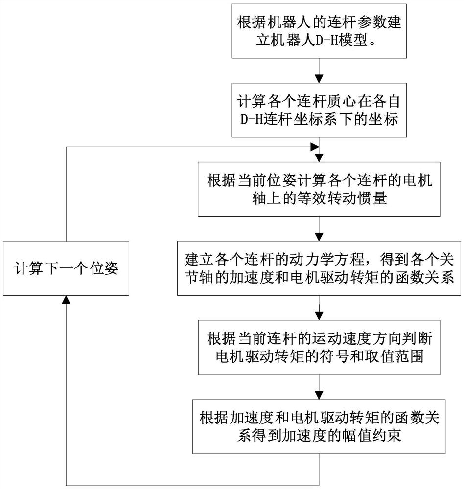
[0041] In order to achieve the above purpose, the embodiment of the present invention provides a joint acceleration constraint planning method according to the change of the equivalent moment of inertia of each joint motor shaft under different poses of the robot, including the following steps:

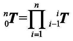
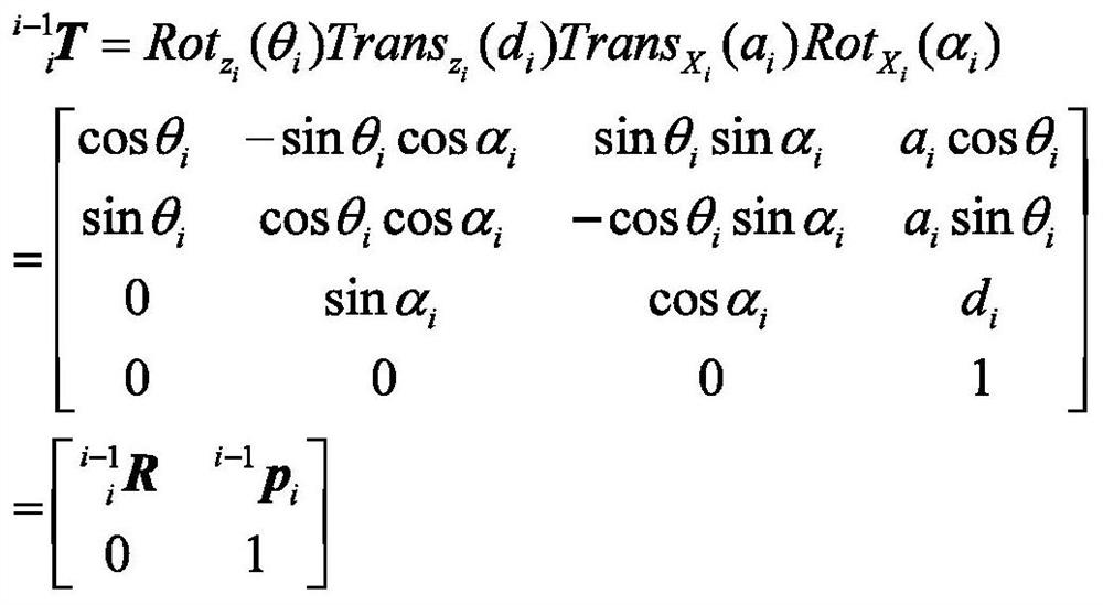
[0042] (a) According to the parameters of each connecting rod of the robot, the corresponding D-H (D...


PUM


Abstract

The invention discloses a robot joint acceleration constraint planning method and system, belonging to the field of robot motion track kinematics planning. Including: establishing the D-H model of each link of the robot, obtaining the homogeneous transformation matrix and the rotation transformation matrix of the D-H link coordinate system; respectively transforming the centroid coordinates of each link from the base coordinate system to the corresponding D-H In the H-link coordinate system, obtain the equivalent moment of inertia on the motor shaft of each joint under the current pose; consider the influence of the load, update the equivalent moment of inertia; establish the dynamic equation of each link, and obtain the acceleration and motor output The functional relationship of the torque; according to the equivalent moment of inertia and the functional relationship, the amplitude constraint of the acceleration is obtained. The invention can comprehensively consider the influence of the gravity of the connecting rod of the robot and the end load on the equivalent moment of inertia of the motor shaft of each rotating joint, and analyze the maximum value of the acceleration of the motor shaft of the joint in this posture, thereby improving the motion efficiency.

Description

technical field [0001] The invention belongs to the field of robot motion track kinematics planning, and more specifically relates to a robot joint acceleration constrained planning method and system. Background technique [0002] With the development of industrial robot technology, its application in manufacturing industry is becoming more and more extensive. For simple object handling tasks, the trajectory of the robot in the task is usually required to achieve continuous acceleration while satisfying the corresponding acceleration amplitude constraints. According to the kinematics of the robot, its terminal acceleration is constrained by the acceleration amplitude of the motor shaft of each joint. When planning the kinematics of the robot trajectory, the acceleration amplitude of the motor shaft of a given joint is usually constrained to a fixed value, so as to plan the kinematics of the entire trajectory. However, in actual tasks, the acceleration and deceleration capa...

Claims


Application Information

Patent Timeline
Patent Type & Authority Patents(China)
IPC IPC(8): B25J9/16B25J17/02
CPCB25J9/1664B25J9/1679B25J17/02
Inventor 杨吉祥孙鸿威丁汉
Owner HUAZHONG UNIV OF SCI & TECH
Why Eureka
Try Eureka