Computer software teaching demonstration meter fixing device for informatization

A fixed device and computer technology, applied in teaching aids, educational aids, instruments, etc., can solve the problems of inconvenient overall movement, inability to adjust the height of the presentation table, etc., and achieve the effect of convenient overall movement

Active Publication Date: 2021-10-19
安徽职业技术学院
View PDF12 Cites 0 Cited by
  • Summary
  • Abstract
  • Description
  • Claims
  • Application Information

AI Technical Summary

Problems solved by technology

But this device is inconvenient to realize the overall movement of the device, and cannot realize the adjustment of the height of the demonstration table

Method used


Image

  • Computer software teaching demonstration meter fixing device for informatization
  • Computer software teaching demonstration meter fixing device for informatization
  • Computer software teaching demonstration meter fixing device for informatization

Examples


Embodiment 1

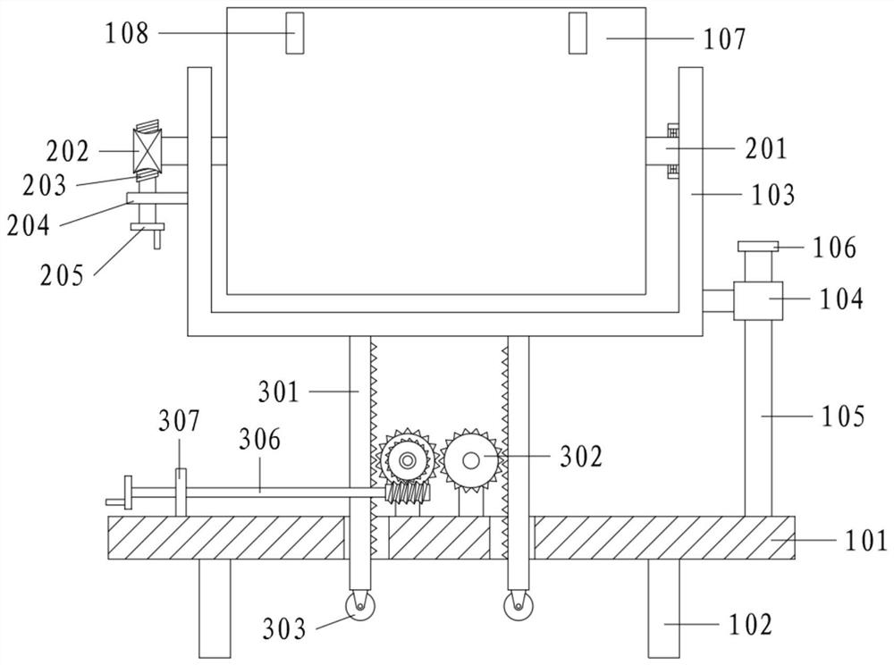
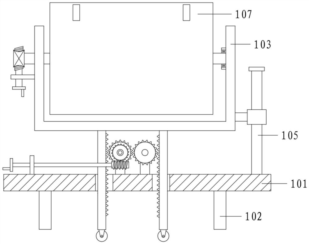
[0038] A computer software teaching demonstration table fixing device for informatization, comprising a base 101, a lifting mechanism and an adjustment structure; a leg 102 is connected below the base 101, a vertical guide rod 105 is connected to the right end of the base 101, and a vertical guide rod 105 is arranged on the guide rod 105 Sliding sleeve 104, the left side of sliding sleeve 104 is connected with U-shaped frame 103; U-shaped frame 103 is provided with rotatable mounting plate 107, and mounting plate 107 is provided with clip 108 for fixing the demonstration table;

[0039] The mounting plate 107 is connected with an adjustment structure; the lower part of the U-shaped frame 103 is connected with a lifting mechanism.

[0040] Among them, the adjustment structure includes the installation shaft 201, the No. 1 worm wheel 202, the No. 1 worm screw 203, the first-class support 204 and the No. 1 rocker 205;

[0041] Between the U-shaped frame 103, a mounting shaft 201 ...

Embodiment 2

[0050] On the basis of embodiment 1,

[0051] Also includes No. 1 bevel gear 401, No. 2 bevel gear 402, driven shaft 403, connecting rod 404, small ball 405, gong piece 406 and spring 407;

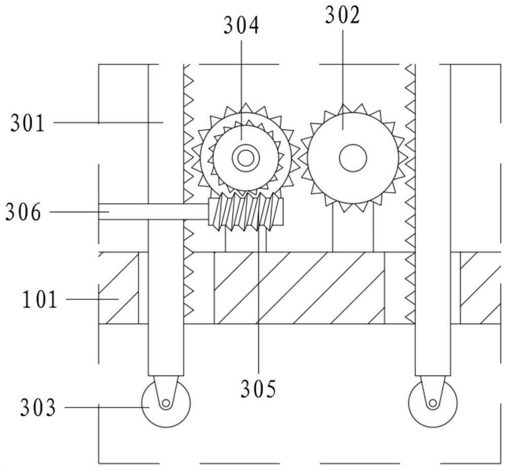
[0052] No. 2 rocker 306 is also fixedly connected with No. 1 bevel gear 401, No. 1 bevel gear 401 is vertically meshed with No. 2 bevel gear 402, No. 2 bevel gear 402 is fixed on the top of driven shaft 403, driven shaft 403 runs through and rotates Connect the base 101; the bottom end of the driven shaft 403 extends to one side of the leg 102, and the ball 405 is connected to the circumference through the connecting rod 404;

[0053] Reference attached Figure 4 , 5 , when the lifting assembly is working, the No. 2 rocker 306 also drives the No. 2 bevel gear 402 to rotate with the driven shaft 403 through the No. 1 bevel gear 401, and the driven shaft 403 rotates with the small ball 405 through the connecting rod 404. The ball 405 collides with the gong piece 406 intermittently and mak...


PUM


Abstract

The invention relates to the technical field of teaching auxiliary devices, in particular to a computer software teaching demonstration meter fixing device for informatization. A demonstration meter is installed on a rotatable installation plate, the installation plate is rotatably connected to a U-shaped frame, a first worm can be driven to rotate through a first rocker, the first worm drives a first worm gear to drive an installation shaft and the installation plate on the installation shaft to deflect, and therefore the demonstration angle change of the demonstration meter is achieved; a second worm gear is driven to rotate through a second rocker, a gear coaxial with the second worm gear is driven to rotate, through gear meshing and gear rack meshing, two racks are made to ascend and descend in the same direction and drive the U-shaped frame to ascend and descend under guiding of a sliding sleeve and a guide rod, and then height adjustment of the mounting plate and the demonstration meter is achieved; when the rack ascends and descends, a roller at the bottom end of the rack ascends and descends along with the rack, and when the roller is higher than the ground, the whole device is supported by supporting legs to be fixed; and when the roller is pressed on the ground and jacks up the device, the whole device is convenient to move.

Description

technical field [0001] The invention relates to the technical field of teaching auxiliary devices, in particular to a computer software teaching demonstration table fixing device for informatization. Background technique [0002] Informatization refers to the use of various computer software to deal with daily tasks, and in the initial training, the instructor will use a demonstration table to help the staff understand. [0003] The Chinese utility model patent with the patent number CN202020578476.4 discloses a computer software teaching demonstration table fixing device for government and enterprise informatization, including a base. The upper end of the base is symmetrically provided with a left vertical board and a right vertical board, and the left vertical board is fixedly connected. On the upper end of the base, a cavity is provided in the base and below the right vertical plate, the inner walls on both sides of the cavity rotate together and are connected with screw ...

Claims


Application Information

Patent Timeline
IPC IPC(8): G09B19/00
CPCG09B19/0053
Inventor 杨阳张坛柳
Owner 安徽职业技术学院
Why Eureka
Try Eureka