Adjustable winding device applied to plastic-coated steel wire rope

A winding device and steel wire rope technology, which is applied in the direction of transportation and packaging, conveying filamentous materials, and thin material processing, etc., can solve the problems of the lack of use value of the winding device and the winding of plastic-coated steel wire ropes, etc., and achieve the improvement of arrangement flatness and The degree of fit, the effect of improving, the effect of improving the winding effect

Active Publication Date: 2021-10-22
南通银龙钢绳有限公司
View PDF5 Cites 9 Cited by
  • Summary
  • Abstract
  • Description
  • Claims
  • Application Information

AI Technical Summary

Problems solved by technology

[0003] When the existing plastic-coated steel wire rope is wound, the motor drives the winding roller to wind the plastic-coated steel wire rope. During the winding process, the plastic-coated steel wire rope is wound around the outer wall of the winding roller , when winding, the traction ring drives the plastic-coated steel wire rope to adjust its position. However, after this adjustment, there is still a gap between the two coiled plastic-coated steel wire ropes, and the plastic-coated steel wire rope is multi-layered after winding. After the first layer of winding is completed, during the second layer of winding, the plastic-coated steel wire rope is easy to squeeze the gap between the previous layer of steel wire ropes, so that the plastic-coated steel wire rope of the second layer is dislocated and pressed into the first winding In the steel wire rope, the various layers of the plastic-coated steel wire rope after winding are intricately arranged, resulting in the winding between the plastic-coated steel wire ropes when the wire is unwound, which in turn leads to the lack of use value of the winding device

Method used


Image

  • Adjustable winding device applied to plastic-coated steel wire rope
  • Adjustable winding device applied to plastic-coated steel wire rope
  • Adjustable winding device applied to plastic-coated steel wire rope

Examples


Embodiment Construction

[0030] The following will clearly and completely describe the technical solutions in the embodiments of the present invention with reference to the accompanying drawings in the embodiments of the present invention. Obviously, the described embodiments are only some, not all, embodiments of the present invention.

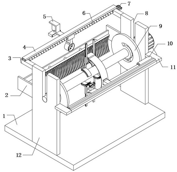
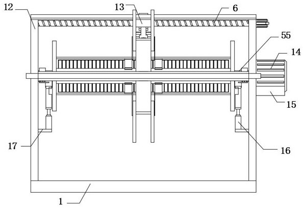
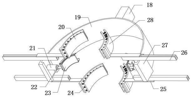
[0031] refer to Figure 1-3 , an adjustable winding device applied to plastic-coated steel wire ropes, including a base 1 and a winding roller 9, both ends of the top outer wall of the base 1 are fixedly connected with support plates 12, and the outer walls of the same side of the two support plates 12 are both Fixedly connected with the fixed plate 11, the outer wall of the opposite side of the two fixed plates 11 is fixedly connected with the same long rod 43, the outer wall of the long rod 43 is fixedly connected with the guide rail 46, and the inner wall of the guide rail 46 is slidably connected with the sliding block 45 , the outer wall of the sliding block 45 ...


PUM


Abstract

The invention belongs to the technical field of plastic-coated steel wire rope winding, in particular to an adjustable winding device applied to a plastic-coated steel wire rope. According to the scheme, the adjustable winding device comprises a base and a winding roller, wherein supporting plates are fixedly connected to the two ends of the outer wall of the top of the base respectively, and fixing plates are fixedly connected to the outer walls of the same sides of the two supporting plates respectively. By arranging a jacking hydraulic cylinder, a jacking rod, a lower shaft sleeve, an upper adjusting shaft sleeve and an extrusion spring, when the winding roller on the outer side of a rotating shaft is replaced, the jacking hydraulic cylinder is adjusted to drive the rotating shaft to be ejected out of an ejection hole, then the upper adjusting shaft sleeve is unfolded towards the outer side, the extrusion spring is compressed, then the winding roller is moved out of the rotating shaft, and the replacement of the winding roller is completed; and after replacement is completed, the rotating shaft falls into the position between the upper adjusting shaft sleeve and the lower shaft sleeve to be limited, and the jacking hydraulic cylinder drives the rotating shaft to return. Therefore, the replacement of the winding roller is rapidly completed, and the winding efficiency of the plastic-coated steel wire rope is improved.

Description

technical field [0001] The invention relates to the technical field of winding plastic-coated steel wire ropes, in particular to an adjustable winding device applied to plastic-coated steel wire ropes. Background technique [0002] Plastic-coated steel wire rope is made of phosphating-coated steel wire rope, galvanized steel wire rope, stainless steel wire rope, and smooth steel wire rope. The steel wire rope is made of pvc plastic; the colors of the plastic-coated steel wire rope are transparent white, black, yellow, green, red, etc., and different plastic colors can be painted according to customer needs. [0003] When the existing plastic-coated steel wire rope is wound, the motor drives the winding roller to wind the plastic-coated steel wire rope. During the winding process, the plastic-coated steel wire rope is wound around the outer wall of the winding roller , when winding, the traction ring drives the plastic-coated steel wire rope to adjust its position. However, ...

Claims


Application Information

Patent Timeline
Patent Type & Authority Applications(China)
IPC IPC(8): B65H54/28B65H54/04B65H67/04B65H59/10
CPCB65H54/2818B65H54/04B65H67/0411B65H59/10B65H2701/35
Inventor 陆华荣
Owner 南通银龙钢绳有限公司
Why Eureka
Try Eureka