New energy battery with anti-collision protection shell

A new energy and protective shell technology, applied in the direction of battery pack components, circuits, electrical components, etc., can solve the problems of poor safety and anti-collision effects, and achieve enhanced impact resistance, good anti-collision effects, and improved elasticity Effect

Inactive Publication Date: 2021-10-22
苏州泛像汽车技术有限公司
View PDF0 Cites 2 Cited by
  • Summary
  • Abstract
  • Description
  • Claims
  • Application Information

AI Technical Summary

Problems solved by technology

[0003] The purpose of the present invention is to solve the disadvantages of poor safety and anti-collision effects in the prior art, and propose a new energy battery with an anti-collision protective case

Method used


Image

  • New energy battery with anti-collision protection shell
  • New energy battery with anti-collision protection shell
  • New energy battery with anti-collision protection shell

Examples


Embodiment 1

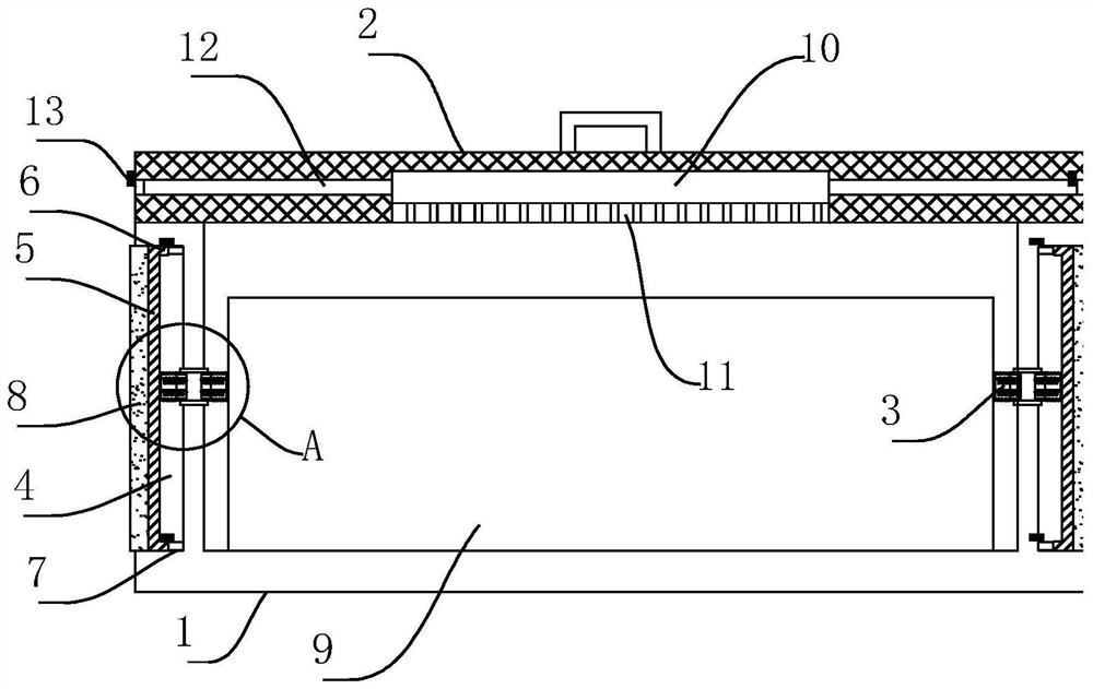
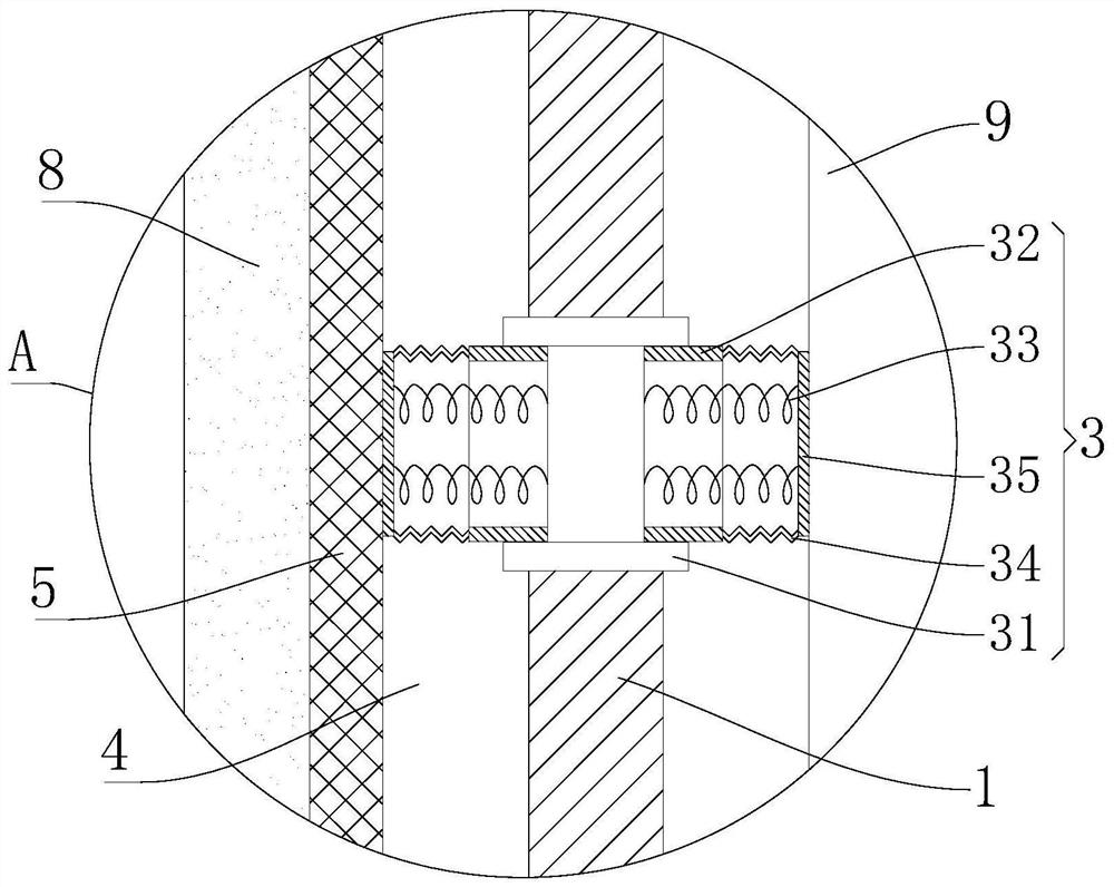
[0017] refer to Figure 1-3 , a new energy battery with an anti-collision protective case, including a new energy battery 9, the new energy battery 9 is placed inside the housing 1, the upper end of the housing 1 is connected to the cover 2 through hinge rotation, and the upper surface of the cover 2 is fixed A handle is installed, and the cover 2 can be easily opened and closed through the handle. The outer surface of the housing 1 is provided with an installation groove 4, and the inner wall surface of the installation groove 4 is pasted with a rubber edge 7, and the inner wall of the installation groove 4 is movable. A flange 6 with an integral structure is fixedly installed on the inner end of the abutment plate 5, and the flange 6 is pasted and connected with the rubber edge 7, and the abutment plate 5 is connected with the rubber edge 7 through the flange 6, and the rubber edge 7 has a good cushioning and supporting effect , when the abutment plate 5 is impacted by the o...

Embodiment 2

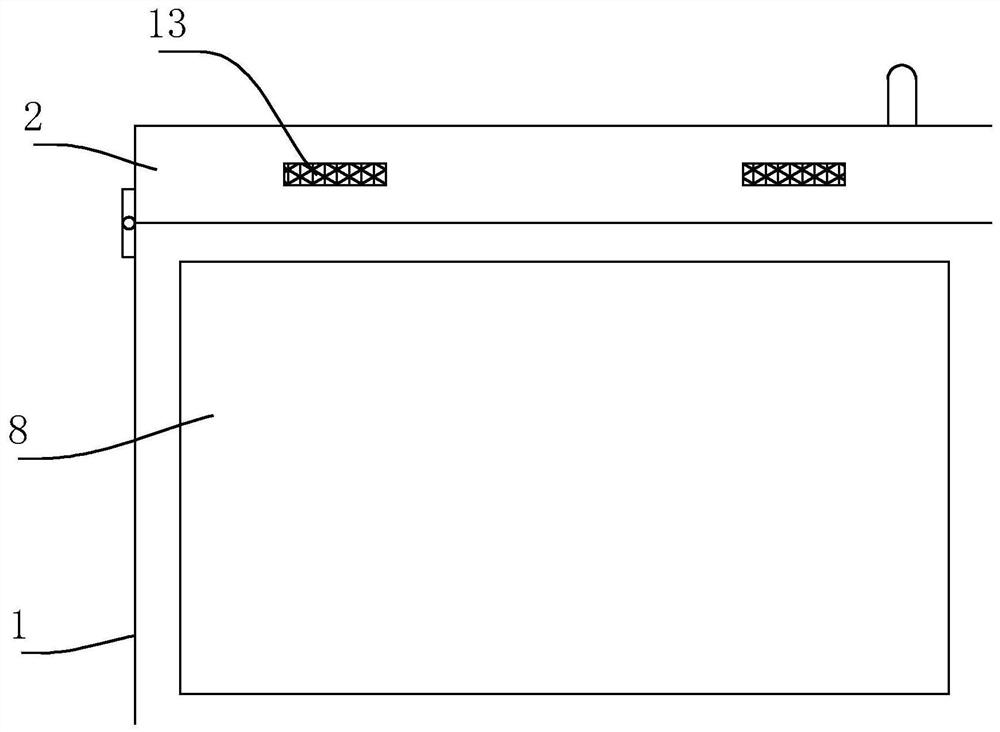
[0021] refer to figure 1 , as another preferred embodiment of the present invention, on the basis of Embodiment 1, an empty slot 10 is opened inside the lower surface of the cover 2, and a connecting plate 11 is fixedly installed at the lower end of the empty slot 10, and the inside of the cover 2 is located in the empty slot Both sides of 10 are provided with ventilation passages 12, through which the inside of the housing 1 can be connected with the outside air through the empty slots 10 and the ventilation passages 12, which can play a certain role in ventilation and heat dissipation. After the battery has been used for a period of time, the housing can be removed. 1 The hot air inside is diffused to prevent the accumulation of hot air, and the temperature inside the battery is getting higher and higher.

Embodiment 3

[0023] refer to figure 1 , as another preferred embodiment of the present invention, on the basis of Embodiment 2, a dust-proof net 13 is fixedly installed on the outer end of the ventilation channel 12, and the dust-proof net 13 plays a good dust-proof role, and can prevent fine particles such as dust Particle impurities enter the interior of the housing 1 through the ventilation channel 12 .


PUM


Abstract

The invention relates to the technical field of new energy batteries, in particular to a new energy battery with an anti-collision protection shell. The new energy battery comprises a new energy battery body, the new energy battery body is placed in a shell, the upper end of the shell is rotatably connected with a sealing cover through a hinge, the outer side surface of the shell is provided with a mounting groove, a rubber edge is pasted on the surface of the inner wall of the mounting groove, an abutting plate is movably arranged in the mounting groove, a flange of an integrated structure is fixedly installed at the end of the inner side of the abutting plate, the flange is connected with the rubber edge in a pasted mode, an elastic piece is arranged in the shell and located in the middle of the mounting groove, the elastic piece comprises a threaded sleeve, connecting rings, a spring, a hose and a supporting plate, the threaded sleeve is in threaded connection with the interior of the shell, the two ends of the threaded sleeve are in threaded connection with the connecting rings, and the outer ends of the connecting rings are connected with the hose in a pasted mode. The battery is good in anti-collision effect and worthy of popularization.

Description

technical field [0001] The invention relates to the technical field of new energy batteries, in particular to a new energy battery with an anti-collision protective case. Background technique [0002] With the development of new energy vehicles, there are more and more innovations in new energy vehicle batteries. New energy vehicle batteries are new types of vehicle batteries that use new energy technologies to reduce "greenhouse gas" emissions. However, new energy batteries need to be When transporting and installing it, due to the large size of the battery body, it is easy to cause bumps and bumps, which will damage the battery and affect its use. Because most of the existing batteries are equipped with buffer devices inside to improve the safety performance of the battery , when the outside of the battery is impacted, the protective effect is not good. Contents of the invention [0003] The purpose of the present invention is to solve the disadvantage of poor safety an...

Claims


Application Information

Patent Timeline
Patent Type & Authority Applications(China)
IPC IPC(8): H01M50/242H01M50/249
CPCY02E60/10
Inventor 高传宝
Owner 苏州泛像汽车技术有限公司
Why Eureka
Try Eureka