Gene engineering technology-based mycin detection system

A detection system and genetic engineering technology, applied in the field of genetic engineering, can solve the problems of affecting the detection of mycin samples, reducing the detection efficiency of mycin samples, and insufficient fixing of reagent tubes, etc.

Inactive Publication Date: 2021-10-26
戴丹丹
View PDF0 Cites 0 Cited by
  • Summary
  • Abstract
  • Description
  • Claims
  • Application Information

AI Technical Summary

Problems solved by technology

[0003] When testing the mycin sample, extract the mycin sample into the inside of the reagent tube for detection. During the detection process, the staff will place the reagent tube containing the mycin sample vertically on the detection rack. The diameter of the reagent tube is generally larger than that of the reagent tube, which makes the fixation of the reagent tube not firm enough, causing the reagent tube to easily collide with the detection rack due to shaking during transportation and cause the reagent tube to break, which directly affects the detection of the mycin sample. Reduced detection efficiency of mycin samples

Method used


Image

  • Gene engineering technology-based mycin detection system
  • Gene engineering technology-based mycin detection system
  • Gene engineering technology-based mycin detection system

Examples


Embodiment 1

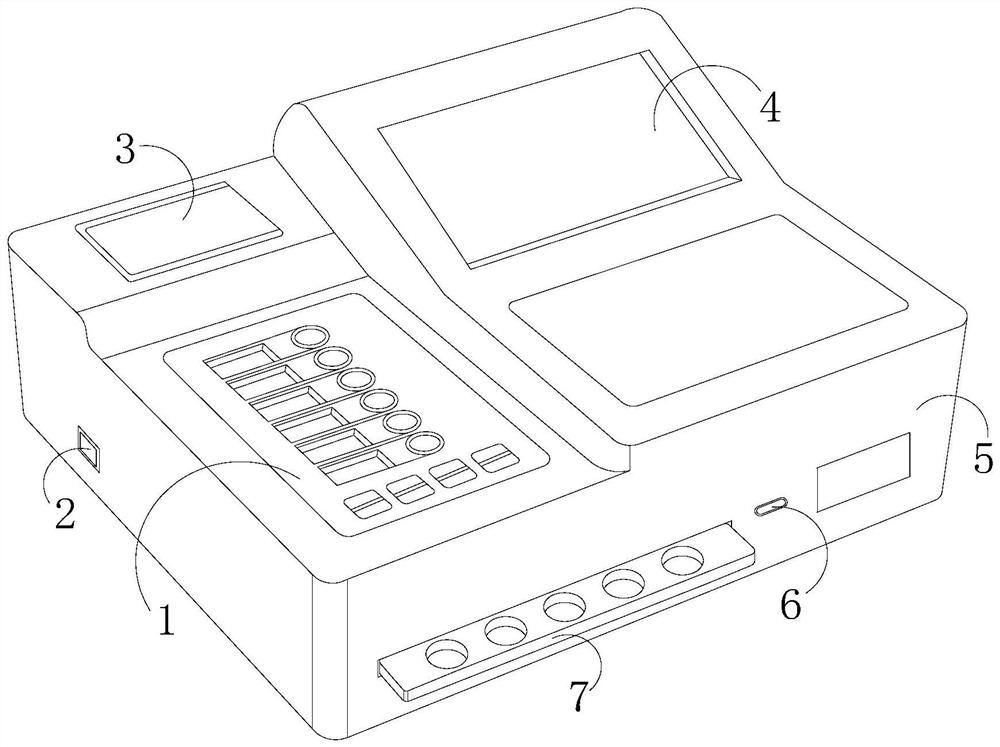
[0030] see figure 1 , the present invention provides a technical solution: a mycin detection system based on genetic engineering technology, the structure of which includes a control panel 1, a power switch 2, a detection element 3, a display screen 4, a body 5, a data interface 6, and a stabilizing device 7 The control panel 1 is set on the body 5, the control panel 1 is connected with the detection element 3 through wires, a display screen 4 is provided on one side of the detection element 3 and both are electrified, and the display screen 4 is embedded Fixed on the body 5, the body 5 communicates with the power switch 2, the body 5 is provided with a stabilizing device 7 connected thereto, one side of the stabilizing device 7 is provided with a data interface 6, and the data interface 6 is connected with display screen 4 through body 5.

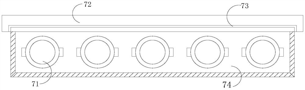
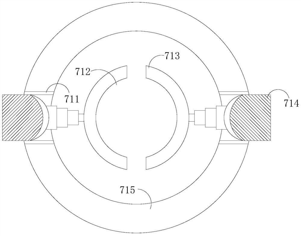
[0031] see figure 2 , the stabilizing device 7 includes a fastening element 71, a mounting base 72, an insertion port 73, and a brack...

Embodiment 2

[0040] see figure 1 , the present invention provides a technical solution: a mycin detection system based on genetic engineering technology, the structure of which includes a control panel 1, a power switch 2, a detection element 3, a display screen 4, a body 5, a data interface 6, and a stabilizing device 7 The control panel 1 is set on the body 5, the control panel 1 is connected with the detection element 3 through wires, a display screen 4 is provided on one side of the detection element 3 and both are electrified, and the display screen 4 is embedded Fixed on the body 5, the body 5 communicates with the power switch 2, the body 5 is provided with a stabilizing device 7 connected thereto, one side of the stabilizing device 7 is provided with a data interface 6, and the data interface 6 is connected with display screen 4 through body 5.

[0041] see figure 2 , the stabilizing device 7 includes a fastening element 71, a mounting base 72, an insertion port 73, and a brack...


PUM


Abstract

The invention discloses a gene engineering technology-based mycin detection system which structurally comprises a control panel, a power switch, a detection element, a display screen, a machine body, a data interface and a stabilizing device. When the gene engineering technology-based mycin detection system is used, a reagent tube is vertically placed on a placement opening, a worker manually pushes a pushing and pressing element inwards, the pushing and pressing element drives clamping arc protection pieces to move inwards under the action of the sliding grooves so that the two clamping arc protection pieces can be stably clamped to the reagent tube, the reagent tube is protected through mutual cooperation of the elastic pulling strips and the jacking pieces, the reagent tube is not prone to shaking in the transportation process, the reagent tube is effectively protected, and the detection efficiency of the mycin sample is improved.

Description

technical field [0001] The invention relates to the technical field of genetic engineering, in particular to a mycin detection system based on genetic engineering technology. Background technique [0002] Mycin is a kind of antibiotic, mainly by inhibiting the synthesis of bacterial protein, it plays the role of inhibiting bacteria, including penicillin, gentamicin, clindamycin, clarithromycin, spectinomycin, etc., through genetic engineering technology For the detection of mycotoxin, the reagent tube is protected by the protective element. When testing the mycotoxin sample, the areas that need to be improved: [0003] When testing the mycin sample, extract the mycin sample into the inside of the reagent tube for detection. During the detection process, the staff will place the reagent tube containing the mycin sample vertically on the detection rack. The diameter of the reagent tube is generally larger than that of the reagent tube, which makes the fixation of the reagent ...

Claims


Application Information

Patent Timeline
IPC IPC(8): G01N33/15
CPCG01N33/15
Inventor 戴丹丹
Owner 戴丹丹
Why Eureka
Try Eureka