Ray inspection system and scattering correction method

A technology of radiographic inspection and scatter correction, applied in the field of radiographic inspection, can solve problems such as image quality degradation and false signals, and achieve the effect of eliminating interference

Pending Publication Date: 2021-10-26
NUCTECH CO LTD
View PDF11 Cites 1 Cited by
  • Summary
  • Abstract
  • Description
  • Claims
  • Application Information

AI Technical Summary

Problems solved by technology

[0002] In the field of X-ray inspection, scatter is often the main cause of image degradation and false signals

Method used


Image

  • Ray inspection system and scattering correction method
  • Ray inspection system and scattering correction method
  • Ray inspection system and scattering correction method

Examples


Embodiment Construction

[0049] Various exemplary embodiments of the present disclosure will now be described in detail with reference to the accompanying drawings. The description of the exemplary embodiments is illustrative only, and in no way restricts the disclosure, its application or uses. The present disclosure can be implemented in many different forms and is not limited to the embodiments described here. Rather, these embodiments are provided so that this disclosure will be thorough and complete, and will fully convey the scope of the disclosure to those skilled in the art. It should be noted that relative arrangements of parts and steps, compositions of materials, numerical expressions and numerical values ​​set forth in these embodiments should be interpreted as illustrative only and not as limiting, unless specifically stated otherwise.

[0050]"First", "second" and similar words used in the present disclosure do not indicate any order, quantity or importance, but are only used to disting...


PUM


Abstract

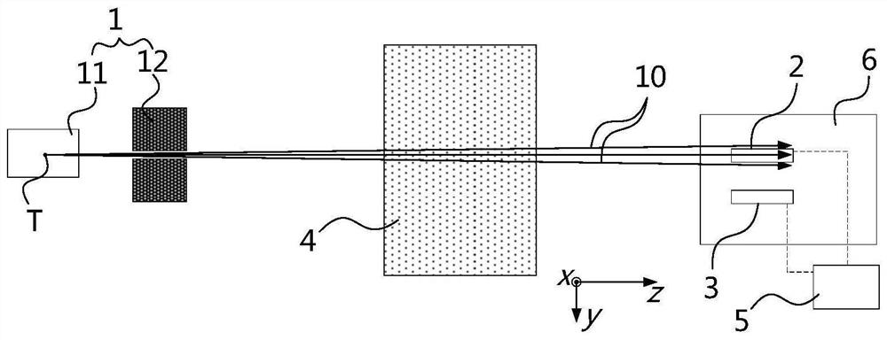
The invention relates to a ray inspection system and a scattering correction method. The ray inspection system comprises: a ray source (1) configured to generate a ray beam (10); a first detector array (2), at least part of the first detector array (2) being located in the coverage range of the ray beam (10); a second detector array (3), the second detector array (3) and the first detector array (2) being located on the same side of an inspection object (4) of the ray inspection system, the second detector array (3) being located outside the coverage range of the ray beam (10), and the second detector array (3) being configured to receive scattering signals of the ray beam (10) in the process of penetrating through the inspection object (4); and a processor (5), in signal connection with the first detector array (2) and the second detector array (3) and configured to perform scattering correction on the received signal of the first detector array (2) according to the scattering signal.

Description

technical field [0001] The present disclosure relates to the field of radiographic inspection, and in particular to a radiographic inspection system and a scattering correction method. Background technique [0002] In the field of X-ray inspection, scatter is often the main cause of image degradation and false signals. The research on scatter correction in the related art is mainly aimed at the research on the CT type inspection system, the X-ray energy used by this inspection system is generally at the level of hundreds of keV, and the X-ray is a cone beam. Scattering correction is mostly realized by complex algorithm analysis. [0003] In other application scenarios, such as container inspection systems used in customs, X-rays with higher energy levels, such as megavolt-level X-rays, are often used. In order to reduce the influence of scattering, in the related art, shielding and collimators are added to reduce scattering signals. Contents of the invention [0004] In...

Claims


Application Information

Patent Timeline
Patent Type & Authority Applications(China)
IPC IPC(8): G01V5/00G01N23/04G01T1/16
CPCG01V5/0016G01N23/04G01T1/16G01N2223/03G01N2223/501G01V5/00G01N23/02
Inventor 李树伟张清军邹湘朱维彬赵博震李祥华王钧效
Owner NUCTECH CO LTD
Why Eureka
Try Eureka